A d v a n c e I n f o r m a t i o n
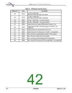
Table 16. Device Geometry Definition
Addresses
Data
Description
27h
0016h
Device Size = 2N byte
Flash Device Interface description (for complete description, please
refer to CFI publication 100)
0000 = x8-only asynchronous interface
0001 = x16-only asynchronous interface
28h
29h
0003h
0000h
0002 = supports x8 and x16 via BYTE# with asynchronous interface
0003 = x 32-only asynchronous interface
0005 = supports x16 and x32 via WORD# with asynchronous
interface
2Ah
2Bh
0000h
0000h
Max. number of byte in multi-byte program = 2N
(00h = not supported)
2Ch
0003h
Number of Erase Block Regions within device
2Dh
2Eh
2Fh
30h
0007h
0000h
0020h
0000h
Erase Block Region 1 Information
(refer to the CFI specification or CFI publication 100)
31h
32h
33h
34h
003Dh
0000h
0000h
0001h
Erase Block Region 2 Information
(refer to the CFI specification or CFI publication 100)
35h
36h
37h
38h
0007h
0000h
0020h
0000h
Erase Block Region 3 Information
(refer to the CFI specification or CFI publication 100)
39h
3Ah
3Bh
3Ch
0000h
0000h
0000h
0000h
Erase Block Region 4 Information
(refer to the CFI specification or CFI publication 100)
March 22, 2004 30606B0
S29CD032G
43

 SPANSION [ SPANSION ]