5th Generation Hi-Speed USB Flash Media and CIR Controller with Integrated Card Power FETs
Datasheet
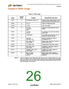
Chapter 9 GPIO Usage
Table 9.1 GPIO Usage
ACTIVE
LEVEL
NAME
SYMBOL
DESCRIPTION AND NOTE
GPIO1
H
Flash Media Activity LED
Indicates media activity. Media or USB
cable must not be removed with LED lit.
GPIO2
GPIO3
GPIO4
H
H
H
EE_CS
V_BUS
Serial EE PROM chip select
USB V bus detect
EE_DIN/
EE_DOUT/
xDID
Serial EE PROM input/output and xD
Identify
GPIO5
GPIO6
GPIO7
GPIO8
H
H
H
L
HS_IND/
SD_CD
HS Indicator LED or SD Card Detect
Switch input
A16/ROMEN
A16 address line connect for DFU or
debug LED indicator optional.
EE_CLK/
Serial EE PROM clock output or
Unconfigured LED.
UNCONF_LED
MS_PWR_CTRL/
CRD_PWR0
Memory Stick Card Power Control, or
Internal Power FET0.
GPIO9
L
L
CF_PWR_CTRL
CompactFlash Card Power Control
GPIO10
SM_PWR_CTRL/
CRD_PWR1
SmartMedia Card Power Control, or
Internal Power FET1.
GPIO11
GPIO12
L
SD/MMC_PWR_CTRL/
CRD_PWR2
SD/MMC Card Power Control, or
Internal Power FET2.
H
MS_ACT_IND/
Media Activity/
CIR_SD
Memory Stick Activity Indicator, or
Media Activity LED or CIR Receiver
Shutdown.
Note 9.1 Function assignment may change with ROM code revision or external firmware use. ROM
Code -00 cannot be used, external firmware must be used to obtain proper functionality.
Subsequent ROM codes will contain proper functionality.Consult firmware release notes for
exact functionality for that release.
Revision 1.3 (07-12-05)
SMSC USB2231/USB2232
DATA2S6HEET

 SMSC [ SMSC CORPORATION ]