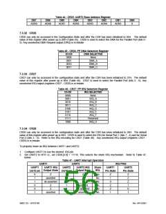
Table 44 - CR25: UART2 Base Address Register
DB7
ADR9
DB6
ADR8
DB5
DB4
DB3
DB2
DB1
ADR3
DB0
0
ADR7
ADR6
ADR5
ADR4
7.3.32 CR26
CR26 can only be accessed in the Configuration State and after the CSR has been initialized to 26H. The default
value of this register after power up is 00H (Table 45). CR26 is used to select the DMA for the Parallel Port (bits 0 -
3). Any unselected DMA Request output (DRQ) is in tristate.
Table 45 - CR26: PP DMA Selection Register
D3-D0
0000
0001
0010
0011
DMA SELECTED
None
DMA_A
DMA_B
DMA_C
7.3.33 CR27
CR27 can only be accessed in the configuration state and after the CSR has been initialized to 27H. The default
value of this register after power up is 00H (Table 46). CR27 is used to select the Parallel Port (bits 3 - 0). Any
unselected IRQ output (registers CR27 - CR29) is in tristate.
Table 46 - CR27: PP IRQ Selection Register
D3-D0
0000
0001
0010
0011
0100
0101
0110
0111
1000
IRQ SELECTED
None
IRQ_A
IRQ_B
IRQ_C
IRQ_D
IRQ_E
IRQ_F
Reserved
IRQ_H
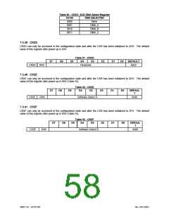
7.3.34 CR28
CR28 can only be accessed in the configuration state and after the CSR has been initialized to 28H. The default
value of this register after power up is 00H. CR28 is used to select the IRQ for Serial Port 1 (bits 7 - 4) and for Serial
Port 2 (bits 3 - 0). Refer to the IRQ encoding for CR27 (Table 46). Any unselected IRQ output (registers CR27 -
CR29) is in tristate.
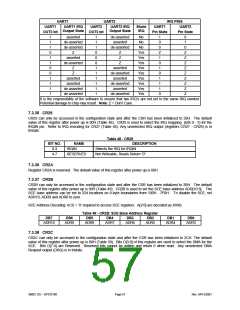
To properly share an IRQ between UART1 and UART2:
1. Configure UART1 to use the desired IRQ pin.
2. Set UART2 to 0FH i.e., set CR28.[3:0] = 1111b. This selects the share IRQ mechanism. Refer to Table 47,
below.
Table 47 - UART Interrupt Operation
UART1
UART2
IRQ PINS
UART1
OUT2 bit
UART1 IRQ
UART2
OUT2 bit
UART2 IRQ
Share
IRQ
UART1
UART2
Output State
Output State
Pin State
Pin State
0
1
1
0
0
1
Z
asserted
de-asserted
Z
0
0
0
1
1
1
Z
Z
Z
No
No
No
No
No
No
Z
1
0
Z
Z
1
Z
Z
Z
1
0
1
asserted
de-asserted
asserted
Z
asserted
SMSC DS – SP37E760
Rev. 04/13/2001

 SMSC [ SMSC CORPORATION ]