Advanced I/O Controller with Motherboard GLUE Logic
Datasheet
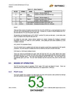
6.5.2 PS/2 mode
This mode supports the PS/2 models 50/60/80 configuration and register set. The DMA bit of the DOR
becomes a “don’t care”. The DMA and interrupt functions are always enabled, and DENSEL is active low.
6.5.3 Model 30 mode
This mode supports PS/2 Model 30 configuration and register set. The DMA enable bit of the DOR
becomes valid (controls the interrupt and DMA functions), and DENSEL is active low.
6.6
6.7
DMA TRANSFERS
DMA transfers are enabled with the Specify command and are initiated by the FDC by activating a DMA
request cycle. DMA read, write and verify cycles are supported. The FDC supports two DMA transfer
modes: Single Transfer and Burst Transfer. Burst mode is enabled via FDC Logical Device -CRF0-Bit[1].
CONTROLLER PHASES
For simplicity, command handling in the FDC can be divided into three phases: Command, Execution, and
Result. Each phase is described in the following sections.
6.7.1 Command Phase
After a reset, the FDC enters the command phase and is ready to accept a command from the host. For
each of the commands, a defined set of command code bytes and parameter bytes has to be written to the
FDC before the command phase is complete. (Please refer to section 6.10 Command Set/Descriptions).
These bytes of data must be transferred in the order prescribed.
Before writing to the FDC, the host must examine the RQM and DIO bits of the Main Status Register.
RQM and DIO must be equal to “1” and “0” respectively before command bytes may be written. RQM is
set false by the FDC after each write cycle until the received byte is processed. The FDC asserts RQM
again to request each parameter byte of the command unless an illegal command condition is detected.
After the last parameter byte is received, RQM remains “0” and the FDC automatically enters the next
phase as defined by the command definition.
The FIFO is disabled during the command phase to provide for the proper handling of the “Invalid
Command” condition.
6.7.2 Execution Phase
All data transfers to or from the FDC occur during the execution phase, which can proceed in DMA mode
as indicated in the Specify command.
After a reset, the FIFO is disabled. Each data byte is transferred by a read/write or DMA cycle depending
on the DMA mode. The Configure command can enable the FIFO and set the FIFO threshold value.
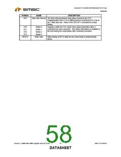
The following paragraphs detail the operation of the FIFO flow control. In these descriptions, <threshold>
is defined as the number of bytes available to the FDC when service is requested from the host and
ranges from 1 to 16. The parameter FIFOTHR, which the user programs, is one less and ranges from 0 to
15.
Revision 1.8 SMSC/Non-SMSC Register Sets (02-24-05)
54
SMSC LPC47M182
DATASHEET

 SMSC [ SMSC CORPORATION ]