Advanced I/O Controller with Motherboard GLUE Logic
Datasheet
SYMBOL
NAME
DESCRIPTION
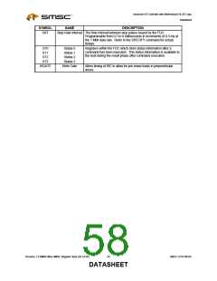
SRT
Step Rate Interval The time interval between step pulses issued by the FDC.
Programmable from 0.5 to 8 milliseconds in increments of 0.5 ms at
the 1 Mbit data rate. Refer to the SPECIFY command for actual
delays.
ST0
ST1
Status 0
Status 1
Status 2
Status 3
Write Gate
Registers within the FDC which store status information after a
command has been executed. This status information is available to
the host during the result phase after command execution.
ST2
ST3
WGATE
Alters timing of WE to allow for pre-erase loads in perpendicular
drives.
Revision 1.8 SMSC/Non-SMSC Register Sets (02-24-05)
58
SMSC LPC47M182
DATASHEET

 SMSC [ SMSC CORPORATION ]