2. The host initiates an I/O write cycle to the selected EPP register.
3. The chip places address or data on PData bus.
4. Chip asserts nDATASTB or nADDRSTRB indicating that PData bus contains valid information, and the WRITE
signal is valid.
5. If nWAIT is asserted, the chip inserts wait states into I/O write cycle until the peripheral deasserts nWAIT or a time-
out occurs.
6. The chip drives the final sync, deasserts nDATASTB or nADDRSTRB and latches the data from the internal data
bus for the PData bus.
7. Chip may modify nWRITE, PDIR and nPDATA in preparation of the next cycle.
EPP 1.7 Read
The timing for a read operation (data) is shown in timing diagram EPP 1.7 Read Data cycle. The chip inserts wait states
into the I/O read cycle when nWAIT is active low during the EPP cycle. This can be used to extend the cycle time. The
read cycle can complete when nWAIT is inactive high.
Read Sequence of Operation:
1. The host sets PDIR bit in the control register to a logic "1". This deasserts nWRITE and tri-states the PData bus.
2. The host initiates an I/O read cycle to the selected EPP register.
3. Chip asserts nDATASTB or nADDRSTRB indicating that PData bus is tri-stated, PDIR is set and the nWRITE signal
is valid.
4. If nWAIT is asserted, the chip inserts wait states into the I/O read cycle until the peripheral deasserts nWAIT or a
time-out occurs.
5. The Peripheral drives PData bus valid.
6. The Peripheral deasserts nWAIT, indicating that PData is valid and the chip may begin the termination phase of the
cycle.
7. The chip drives the final sync and deasserts nDATASTB or nADDRSTRB.
8. Peripheral tri-states the PData bus.
9. Chip may modify nWRITE, PDIR and nPDATA in preparation of the next cycle.
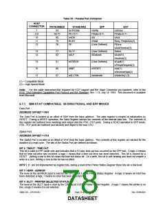
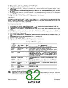
Table 34 − EPP Pin Descriptions
EPP
SIGNAL
EPP NAME
nWrite
TYPE
EPP DESCRIPTION
nWRITE
PD<0:7>
INTR
O
I/O
I
This signal is active low. It denotes a write operation.
Bi-directional EPP byte wide address and data bus.
Address/Data
Interrupt
This signal is active high and positive edge triggered. (Pass
through with no inversion, Same as SPP).
WAIT
nWait
I
This signal is active low. It is driven inactive as a positive
acknowledgement from the device that the transfer of data is
completed. It is driven active as an indication that the device is
ready for the next transfer.
DATASTB nData Strobe
RESET nReset
O
O
O
This signal is active low. It is used to denote data read or write
operation.
This signal is active low. When driven active, the EPP device
is reset to its initial operational mode.
ADDRSTB nAddress
Strobe
This signal is active low. It is used to denote address read or
write operation.
PE
Paper End
I
I
Same as SPP mode.
Same as SPP mode.
SLCT
Printer Selected
Status
nERR
Error
I
Same as SPP mode.
Note 1: SPP and EPP can use 1 common register.
Note 2: nWrite is the only EPP output that can be over-ridden by SPP control port during an EPP cycle. For correct
EPP read cycles, PCD is required to be a low.
SMSC DS – LPC47S45x
Page 82 of 259
Rev. 07/09/2001
DATASHEET

 SMSC [ SMSC CORPORATION ]