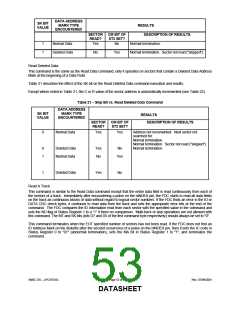
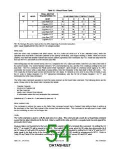
Table 22 − Result Phase Table
FINAL SECTOR
TRANSFERRED TO
MT
HEAD
ID INFORMATION AT RESULT PHASE
HOST
C
H
R
N
0
0
1
0
1
Less than EOT
Equal to EOT
Less than EOT
Equal to EOT
Less than EOT
Equal to EOT
Less than EOT
Equal to EOT
NC
NC
NC
NC
NC
NC
LSB
NC
LSB
R + 1
01
NC
NC
NC
NC
NC
NC
NC
NC
C + 1
NC
R + 1
01
C + 1
NC
1
R + 1
01
NC
NC
R + 1
01
C + 1
NC: No Change, the same value as the one at the beginning of command execution.
LSB: Least Significant Bit, the LSB of H is complemented.
Write Data
After the Write Data command has been issued, the FDC loads the head (if it is in the unloaded state), waits the
specified head load time if unloaded (defined in the Specify command), and begins reading ID fields. When the sector
address read from the diskette matches the sector address specified in the command, the FDC reads the data from the
host via the FIFO and writes it to the sector's data field.
After writing data into the current sector, the FDC computes the CRC value and writes it into the CRC field at the end of
the sector transfer. The Sector Number stored in "R" is incremented by one, and the FDC continues writing to the next
data field. The FDC continues this "Multi-Sector Write Operation". Upon receipt of a terminal count signal or if a FIFO
over/under run occurs while a data field is being written, then the remainder of the data field is filled with zeros. The
FDC reads the ID field of each sector and checks the CRC bytes. If it detects a CRC error in one of the ID fields, it sets
the IC code in Status Register 0 to "01" (abnormal termination), sets the DE bit of Status Register 1 to "1", and
terminates the Write Data command.
The Write Data command operates in much the same manner as the Read Data command. The following items are the
same. Please refer to the Read Data Command for details:
-
-
-
-
-
Transfer Capacity
EN (End of Cylinder) bit
ND (No Data) bit
Head Load, Unload Time Interval
ID information when the host terminates the command
Definition of DTL when N = 0 and when N does not = 0
Write Deleted Data
This command is almost the same as the Write Data command except that a Deleted Data Address Mark is written at
the beginning of the Data Field instead of the normal Data Address Mark. This command is typically used to mark a bad
sector containing an error on the floppy disk.
Verify
The Verify command is used to verify the data stored on a disk. This command acts exactly like a Read Data command
except that no data is transferred to the host. Data is read from the disk and CRC is computed and checked against the
previously-stored value.
Because data is not transferred to the host, the TC cycle cannot be used to terminate this command. By setting the EC
bit to "1", an implicit TC will be issued to the FDC. This implicit TC will occur when the SC value has decremented to 0
(an SC value of 0 will verify 256 sectors). This command can also be terminated by setting the EC bit to "0" and the EOT
value equal to the final sector to be checked. If EC is set to "0", DTL/SC should be programmed to 0FFH. Refer to
Table 22 and Table 23 for information concerning the values of MT and EC versus SC and EOT value.
SMSC DS – LPC47S45x
Page 54 of 259
Rev. 07/09/2001
DATASHEET

 SMSC [ SMSC CORPORATION ]