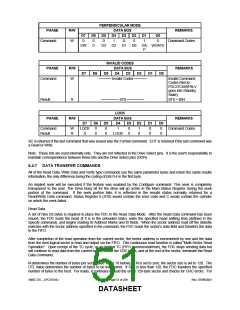
PERPENDICULAR MODE
DATA BUS
PHASE
R/W
REMARKS
D7
0
D6
0
D5
0
D4
1
D3
0
D2
0
D1
D0
Command
W
1
0
Command Codes
OW
0
D3
D2
D1
D0
GA WGATE
P
INVALID CODES
DATA BUS
PHASE
R/W
REMARKS
D7
D6
D5
D4
D3
D2
D1
D0
Command
W
───── Invalid Codes ─────
Invalid Command
Codes (NoOp -
FDC37C669FRLV
goes into Standby
State)
Result
R
─────── ST0 ───────
ST0 = 80H
LOCK
PHASE
R/W
DATA BUS
REMARKS
D7
LOCK
0
D6
0
0
D5
0
0
D4
1
LOCK
D3
0
0
D2
1
0
D1
0
0
D0
0
0
Command
Result
W
R
Command Codes
SC is returned if the last command that was issued was the Format command. EOT is returned if the last command was
a Read or Write.
Note: These bits are used internally only. They are not reflected in the Drive Select pins. It is the user's responsibility to
maintain correspondence between these bits and the Drive Select pins (DOR).
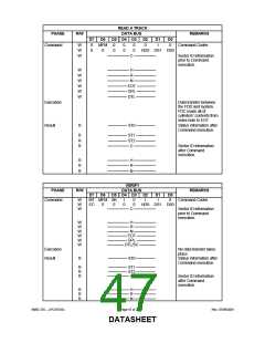
6.4.7 DATA TRANSFER COMMANDS
All of the Read Data, Write Data and Verify type commands use the same parameter bytes and return the same results
information, the only difference being the coding of bits 0-4 in the first byte.
An implied seek will be executed if the feature was enabled by the Configure command. This seek is completely
transparent to the user. The Drive Busy bit for the drive will go active in the Main Status Register during the seek
portion of the command. If the seek portion fails, it is reflected in the results status normally returned for a
Read/Write Data command. Status Register 0 (ST0) would contain the error code and C would contain the cylinder
on which the seek failed.
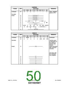
Read Data
A set of nine (9) bytes is required to place the FDC in the Read Data Mode. After the Read Data command has been
issued, the FDC loads the head (if it is in the unloaded state), waits the specified head settling time (defined in the
Specify command), and begins reading ID Address Marks and ID fields. When the sector address read off the diskette
matches with the sector address specified in the command, the FDC reads the sector's data field and transfers the data
to the FIFO.
After completion of the read operation from the current sector, the sector address is incremented by one and the data
from the next logical sector is read and output via the FIFO. This continuous read function is called "Multi-Sector Read
Operation". Upon receipt of the TC cycle, or an implied TC (FIFO overrun/underrun), the FDC stops sending data but
will continue to read data from the current sector, check the CRC bytes, and at the end of the sector, terminate the Read
Data Command.
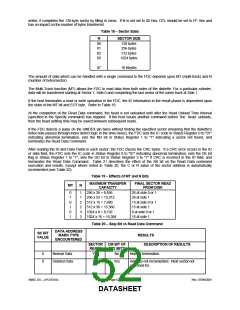
N determines the number of bytes per sector (see Table 18 below). If N is set to zero, the sector size is set to 128. The
DTL value determines the number of bytes to be transferred. If DTL is less than 128, the FDC transfers the specified
number of bytes to the host. For reads, it continues to read the entire 128-byte sector and checks for CRC errors. For
SMSC DS – LPC47S45x
Page 51 of 259
Rev. 07/09/2001
DATASHEET

 SMSC [ SMSC CORPORATION ]