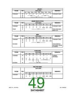
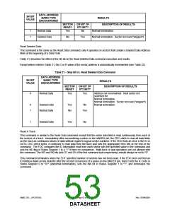
DATA ADDRESS
MARK TYPE
ENCOUNTERED
SK BIT
VALUE
RESULTS
DESCRIPTION OF RESULTS
SECTOR CM BIT OF
READ?
ST2 SET?
1
1
Normal Data
Deleted Data
Yes
No
Normal termination.
No
Yes
Normal termination. Sector not read ("skipped").
Read Deleted Data
This command is the same as the Read Data command, only it operates on sectors that contain a Deleted Data Address
Mark at the beginning of a Data Field.
Table 21 describes the effect of the SK bit on the Read Deleted Data command execution and results.
Except where noted in Table 21, the C or R value of the sector address is automatically incremented (see Table 22).
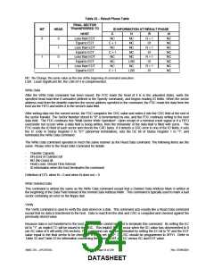
Table 21 − Skip Bit vs. Read Deleted Data Command
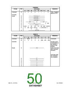
DATA ADDRESS
SK BIT
VALUE
MARK TYPE
ENCOUNTERED
RESULTS
DESCRIPTION OF RESULTS
SECTOR CM BIT OF
READ?
ST2 SET?
0
Normal Data
Yes
Yes
Address not incremented. Next sector not
searched for.
Normal termination.
Normal termination. Sector not read ("skipped").
Normal termination.
0
1
Deleted Data
Normal Data
Yes
No
No
Yes
1
Deleted Data
Yes
No
Read A Track
This command is similar to the Read Data command except that the entire data field is read continuously from each of
the sectors of a track. Immediately after encountering a pulse on the nINDEX pin, the FDC starts to read all data fields
on the track as continuous blocks of data without regard to logical sector numbers. If the FDC finds an error in the ID or
DATA CRC check bytes, it continues to read data from the track and sets the appropriate error bits at the end of the
command. The FDC compares the ID information read from each sector with the specified value in the command and
sets the ND flag of Status Register 1 to a “1” if there no comparison. Multi-track or skip operations are not allowed with
this command. The MT and SK bits (bits D7 and D5 of the first command byte respectively) should always be set to "0".
This command terminates when the EOT specified number of sectors has not been read. If the FDC does not find an
ID Address Mark on the diskette after the second occurrence of a pulse on the nINDEX pin, then it sets the IC code in
Status Register 0 to "01" (abnormal termination), sets the MA bit in Status Register 1 to "1", and terminates the
command.
SMSC DS – LPC47S45x
Page 53 of 259
Rev. 07/09/2001
DATASHEET

 SMSC [ SMSC CORPORATION ]