Sense Interrupt Status
An interrupt signal is generated by the FDC for one of the following reasons:
1. Upon entering the Result Phase of:
a. Read Data command
b. Read A Track command
c. Read ID command
d. Read Deleted Data command
e. Write Data command
f. Format A Track command
g. Write Deleted Data command
h. Verify command
2. End of Seek, Relative Seek, or Recalibrate command
The Sense Interrupt Status command resets the interrupt signal and, via the IC code and SE bit of Status Register 0,
identifies the cause of the interrupt.
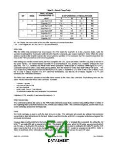
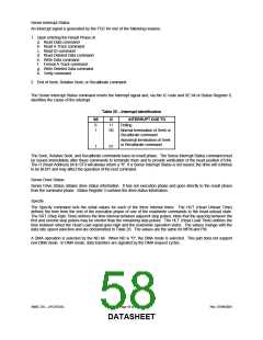
Table 25 − Interrupt Identification
SE
0
1
IC
11
00
INTERRUPT DUE TO
Polling
Normal termination of Seek or
Recalibrate command
Abnormal termination of Seek
or Recalibrate command
1
01
The Seek, Relative Seek, and Recalibrate commands have no result phase. The Sense Interrupt Status command must
be issued immediately after these commands to terminate them and to provide verification of the head position (PCN).
The H (Head Address) bit in ST0 will always return a "0". If a Sense Interrupt Status is not issued, the drive will continue
to be BUSY and may affect the operation of the next command.
Sense Drive Status
Sense Drive Status obtains drive status information. It has not execution phase and goes directly to the result phase
from the command phase. Status Register 3 contains the drive status information.
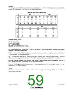
Specify
The Specify command sets the initial values for each of the three internal times. The HUT (Head Unload Time)
defines the time from the end of the execution phase of one of the read/write commands to the head unload state.
The SRT (Step Rate Time) defines the time interval between adjacent step pulses. Note that the spacing between the
first and second step pulses may be shorter than the remaining step pulses. The HLT (Head Load Time) defines the
time between when the Head Load signal goes high and the read/write operation starts. The values change with the
data rate speed selection and are documented in Table 26. The values are the same for MFM and FM.
A DMA operation is selected by the ND bit. When ND is "0", the DMA mode is selected. This part does not support
non-DMA mode. In DMA mode, data transfers are signaled by the DMA request cycles.
SMSC DS – LPC47S45x
Page 58 of 259
Rev. 07/09/2001
DATASHEET

 SMSC [ SMSC CORPORATION ]