11 PACKAGE OUTLINE
Note: The following package information is preliminary. Contact SMSC for the latest information.
FIGURE 48 – 128 PIN QFP PACKAGE OUTLINE
MIN
~
NOMINAL
MAX
3.4
REMARKS
Overall Package Height
Standoff
A
A1
A2
D
~
~
0.05
2.55
23.70
11.85
19.90
17.70
8.85
13.90
~
0.5
~
3.05
24.10
12.05
20.10
18.10
9.05
14.10
~
Body Thickness
23.90
11.95
20.0
17.90
8.95
14.00
~
X Span
D/2
D1
E
1/2 X Span Measured from Centerline
X body Size
Y Span
E/2
E1
H
1/2 Y Span Measured from Centerline
Y body Size
Lead Frame Thickness
Lead Foot Length
Lead Length
L
0.73
~
0.88
1.95
0.5 Basic
~
1.03
~
L1
e
Lead Pitch
0o
0.10
0.13
7o
0.30
~
Lead Foot Angle
Lead Width
W
~
~
R1
Lead Shoulder Radius
R2
ccc
ccc
0.13
~
~
~
~
~
0.30
0.0762
0.08
Lead Foot Radius
Coplanarity (Assemblers)
Coplanarity (Test House)
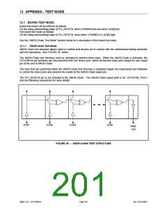
Notes:
1 Controlling Unit: millimeter
2 Tolerance on the position of the leads is + 0.04 mm maximum.
3 Package body dimensions D1 and E1 do not include the mold protrusion.
Maximum mold protrusion is 0.25 mm.
4 Dimension for foot length L measured at the gauge plane 0.25 mm above the seating plane.
5 Details of pin 1 identifier are optional but must be located within the zone indicated
SMSC DS – LPC47M14X
Page 200
Rev. 03/19/2001

 SMSC [ SMSC CORPORATION ]