CLK
1
t3 t4
CLK
2
CLK
9
CLK
10
CLK
11
KCLK/
MCLK
t5
t2
t6
t1
KDAT/ Start Bit
Bit 0
Bit 7
Parity Bit Stop Bit
MDAT
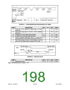
FIGURE 43 – KEYBOARD/MOUSE RECEIVE/SEND DATA TIMING
NAME
t1
DESCRIPTION
Time from DATA transition to falling edge of CLOCK
MIN
5
TYP
MAX
25
UNITS
µsec
(Receive)
t2
Time from rising edge of CLOCK to DATA transition
(Receive)
5
T4-5
µsec
t3
t4
t5
Duration of CLOCK inactive (Receive/Send)
Duration of CLOCK active (Receive/Send)
30
30
>0
50
50
50
µsec
µsec
µsec
Time to keyboard inhibit after clock 11 to ensure the
keyboard does not start another transmission (Receive)
t6
Time from inactive to active CLOCK transition, used to
time when the auxiliary device samples DATA (Send)
5
25
µsec
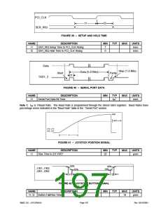
Idle (No Data)
Data
Idle (No Data)
Stop Bit
Start Bit
t1
Data
MIDI_Tx
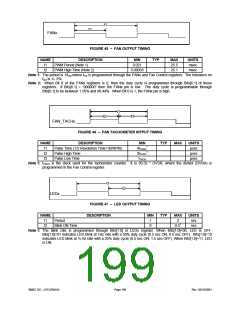
FIGURE 44 – MIDI DATA BYTE
DESCRIPTION
NAME
t1
MIN
31.7
TYP
32
MAX
32.3
UNITS
µsec
MIDI Data Bit Time
Note: The MIDI bit clock is 31.25kHz +/- 1%
SMSC DS – LPC47M14X
Page 198
Rev. 03/19/2001

 SMSC [ SMSC CORPORATION ]