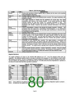
Table 41 - ECP Pin Descriptions
DESCRIPTION
During write operations nStrobe registers data or address into the slave on the asserting
edge (handshakes with Busy).
NAME
nStrobe
TYPE
O
PData 7:0
nAck
I/O
I
Contains address or data or RLE data.
Indicates valid data driven by the peripheral when asserted. This signal handshakes with
nAutoFd in reverse.
PeriphAck (Busy)
I
I
This signal deasserts to indicate that the peripheral can accept data. This signal
handshakes with nStrobe in the forward direction. In the reverse direction this signal
indicates whether the data lines contain ECP command information or data. The
peripheral uses this signal to flow control in the forward direction. It is an "interlocked"
handshake with nStrobe. PeriphAck also provides command information in the reverse
direction.
Used to acknowledge a change in the direction the transfer (asserted = forward). The
peripheral drives this signal low to acknowledge nReverseRequest. It is an "interlocked"
handshake with nReverseRequest. The host relies upon nAckReverse to determine when
it is permitted to drive the data bus.
PError
(nAckReverse)
Select
I
Indicates printer on line.
nAutoFd
(HostAck)
O
Requests a byte of data from the peripheral when asserted, handshaking with nAck in the
reverse direction. In the forward direction this signal indicates whether the data lines
contain ECP address or data. The host drives this signal to flow control in the reverse
direction. It is an "interlocked" handshake with nAck. HostAck also provides command
information in the forward phase.
nFault
(nPeriphRequest)
I
Generates an error interrupt when asserted. This signal provides a mechanism for
peer-to-peer communication. This signal is valid only in the forward direction. During ECP
Mode the peripheral is permitted (but not required) to drive this pin low to request a reverse
transfer. The request is merely a "hint" to the host; the host has ultimate control over the
transfer direction. This signal would be typically used to generate an interrupt to the host
CPU.
nInit
O
O
Sets the transfer direction (asserted = reverse, deasserted = forward). This pin is driven
low to place the channel in the reverse direction. The peripheral is only allowed to drive the
bi-directional data bus while in ECP Mode and HostAck is low and nSelectIn is high.
Always deasserted in ECP mode.
nSelectIn
Register Definitions
The register definitions are based on the standard IBM addresses for LPT. All of the standard printer ports are
supported. The additional registers attach to an upper bit decode of the standard LPT port definition to avoid conflict
with standard ISA devices. The port is equivalent to a generic parallel port interface and may be operated in that mode.
The port registers vary depending on the mode field in the ecr. The table below lists these dependencies. Operation of
the devices in modes other that those specified is undefined.
Table 42 - ECP Register Definitions
NAME
ADDRESS (Note 1)
+000h R/W
+000h R/W
+001h R/W
+002h R/W
+400h R/W
+400h R/W
+400h R/W
+400h R
ECP MODES
FUNCTION
Data Register
ECP FIFO (Address)
Status Register
data
000-001
011
All
ecpAFifo
dsr
dcr
All
Control Register
cFifo
ecpDFifo
tFifo
cnfgA
cnfgB
ecr
010
011
110
111
111
All
Parallel Port Data FIFO
ECP FIFO (DATA)
Test FIFO
Configuration Register A
Configuration Register B
Extended Control Register
+401h R/W
+402h R/W
Note 1: These addresses are added to the parallel port base address as selected by configuration register or jumpers.
Note 2: All addresses are qualified with AEN. Refer to the AEN pin definition.
Page 80

 SMSC [ SMSC CORPORATION ]