Bit 5 indicates when the XMIT FIFO is empty.
Bit 6 indicates that both the XMIT FIFO and shift register are empty.
Bit 7 indicates whether there are any errors in the RCVR FIFO.
There is no trigger level reached or timeout condition indicated in the FIFO Polled Mode, however, the RCVR and XMIT
FIFOs are still fully capable of holding characters.
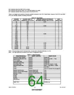
Table 30 - Baud Rates
DESIRED
BAUD RATE
50
DIVISOR USED TO
PERCENT ERROR DIFFERENCE
HIGH
GENERATE 16X CLOCK
BETWEEN DESIRED AND ACTUAL1
SPEED BIT2
2304
1536
1047
857
768
384
192
96
0.001
X
X
X
X
X
X
X
X
X
X
X
X
X
X
X
X
X
X
X
1
75
-
-
110
134.5
150
0.004
-
300
-
600
-
1200
-
1800
64
-
2000
58
0.005
2400
48
-
3600
32
-
-
4800
24
7200
16
-
9600
12
-
19200
38400
57600
115200
230400
460800
6
-
3
0.030
0.16
0.16
0.16
0.16
2
1
32770
32769
1
Note1: The percentage error for all baud rates, except where indicated otherwise, is 0.2%.
Note 2: The High Speed bit is located in the Device Configuration Space.
Table 31 - Reset Function
REGISTER/SIGNAL
Interrupt Enable Register
Interrupt Identification Reg.
FIFO Control
RESET CONTROL
RESET STATE
RESET
All bits low
RESET
RESET
RESET
RESET
RESET
RESET
RESET
Bit 0 is high; Bits 1 - 7 low
All bits low
All bits low
All bits low
All bits low except 5, 6 high
Bits 0 - 3 low; Bits 4 - 7 input
See Note 1
Line Control Reg.
MODEM Control Reg.
Line Status Reg.
MODEM Status Reg.
TXD1
TXD2
RESET
See IR Transmit Pins on page 69
INTRPT (RCVR errs)
RESET/Read LSR
Low
INTRPT (RCVR Data Ready) RESET/Read RBR
Low
INTRPT (THRE)
OUT2B
RESET/ReadIIR/Write THR
Low
RESET
High
RTSB
RESET
High
DTRB
RESET
High
OUT1B
RESET
High
RCVR FIFO
RESET/
All Bits Low
FCR1*FCR0/_FCR0
RESET/
XMIT FIFO
All Bits Low
FCR1*FCR0/_FCR0
SMSC LPC47B27x
- 64 -
Rev. 08-10-04
DATASHEET

 SMSC [ SMSC CORPORATION ]