Non-PCI Single-Chip Full Duplex Ethernet Controller with Magic Packet
DIS LINK - This bit is used to disable the 10BASE-T link test functions. When this bit is high the
LAN91C96 disables link test functions by not generating nor monitoring the network for link
pulses. In this mode the LAN91C96 will transmit packets regardless of the link test, the EPHSR
LINK_OK bit will be set and the LINK LED will stay on. When low the link test functions are
enabled. If the link status indicates FAIL, the EPHSR LINK_OK bit will be low, while transmit
packets enqueued will be processed by the LAN91C96, transmit data will not be sent out to the
cable.
INT SEL1-0 - In LOCAL BUS mode, used to select one out of four interrupt pins. The three
unused interrupts are tristated.
INT SEL1
INT SEL0
INTERRUPT PIN USED
0
0
1
1
0
1
0
1
INTR0
INTR1
INTR2
INTR3
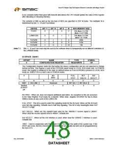
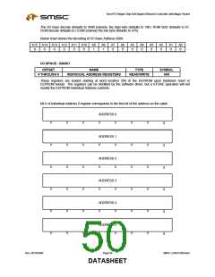
I/O SPACE - BANK1
OFFSET
2
NAME
TYPE
READ/WRITE
SYMBOL
BAR
BASE ADDRESS REGISTER
For LOCAL BUS mode only, this register holds the I/O address decode option chosen for the I/O and ROM
space. It is part of the EEPROM saved setup, and is not usually modified during run-time.
A15
0
A14
0
A13
0
A9
1
A8
1
A7
0
A6
0
A5
0
ROM SIZE
RA18
1
RA17
0
RA16
0
RA15
1
RA14
1
0
1
1
A15 - A13 and A9 - A5 - These bits are compared in LOCAL BUS mode against the I/O address on the
bus to determine the IOBASE for LAN91C96 registers. The 64k I/O space is fully decoded by the
LAN91C96 down to a 16 location space, therefore the unspecified address lines A4, A10, A11 and A12
must be all zeros.
ROM SIZE - Determines the ROM decode area in LOCAL BUS mode memory space as follows:
00 = ROM disable
01 = 16k: RA14-18 define ROM select.
10 = 32k: RA15-18 define ROM select.
11 = 64k: RA16-18 define ROM select.
RA18-RA14 - These bits are compared in LOCAL BUS mode against the memory address on the bus to
determine if the ROM is being accessed, as a function of the ROM SIZE. ROM accesses are read only
memory accesses defined by MEMRD* going low.
For a full decode of the address space unspecified upper address lines have to be: A19 = "1", A20-A23
lines are not directly decoded, however LOCAL BUS systems will only activate SMEMRD* only when A20-
A23=0.
All bits in this register are loaded from the serial EEPROM in LOCAL BUS Mode only. In PCMCIA mode,
the I/O base is set to the default value (as in LOCAL BUS mode) as defined below.
SMSC LAN91C965v&3v
Page 49
Rev. 09/10/2004
DATASHEET

 SMSC [ SMSC CORPORATION ]