Non-PCI Single-Chip Full Duplex Ethernet Controller with Magic Packet
Chapter 6 Frame Format in Buffer Memory for
Ethernet
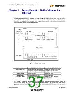
The frame format in memory is similar to that in the TRANSMIT and RECEIVE areas. The first word is
reserved for the status word, the next word is used to specify the total number of bytes, and that in turn is
followed by the data area. The data area holds the packet itself, and its length is determined by the byte
count. The frame memory format is word oriented.
bit0
bit15
2nd Byte
RAM
OFFSET
1st Byte
(DECIMAL)
0
STATUS WORD
2
4
BYTE COUNT (always even)
RESERVED
DATA AREA
1534 Max
LAST DATA BYTE (if odd)
CONTROL BYTE
Last Byte
Figure 6.1 – Data Frame Format
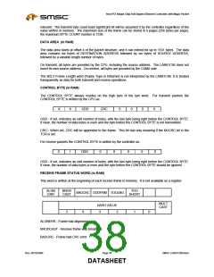
TRANSMIT PACKET
Written by CSMA upon transmit Written by CSMA upon receive
completion (see Status Register) completion (see RX Frame
Status Word)
RECEIVE PACKET
STATUS WORD
BYTE COUNT
DATA AREA
CONTROL BYTE
Written by CPU
Written/modified by CPU
Written by CSMA
Written by CSMA
Written by CPU to control
Written by CSMA. Also has
ODD/EVEN data bytes
ODD/EVEN bit
BYTE COUNT - Divided by two, it defines the total number of words, including the STATUS WORD, the
BYTE COUNT WORD, the DATA AREA and the CONTROL BYTE. The receive byte count always
appears as even, the ODDFRM bit of the receive status word indicates if the low byte of the last word is
SMSC LAN91C965v&3v
Page 37
Rev. 09/10/2004
DATASHEET

 SMSC [ SMSC CORPORATION ]