Non-PCI Single-Chip Full Duplex Ethernet Controller with Magic Packet
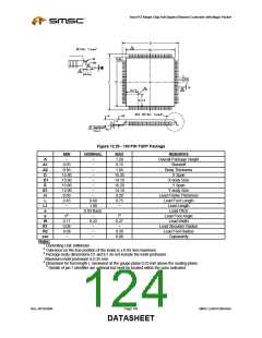
Figure 12.28 - 100 PIN QFP Package
MIN
~
NOMINAL
MAX
3.4
0.5
REMARKS
Overall Package Height
Standoff
A
A1
A2
D
D1
E
E1
H
L
~
~
~
~
~
~
~
~
0.05
2.55
23.65
19.90
17.65
13.90
0.11
0.73
~
3.05
24.15
20.10
18.15
14.10
0.23
1.03
~
Body Thickness
X Span
X body Size
Y Span
Y body Size
Lead Frame Thickness
Lead Foot Length
Lead Length
0.88
1.95
0.65 Basic
L1
e
Lead Pitch
Lead Foot Angle
0o
0.20
0.10
0.15
~
~
~
~
~
~
7o
θ
W
R1
R2
ccc
Notes:
0.40
0.25
0.40
0.10
Lead Width
Lead Shoulder Radius
Lead Foot Radius
Coplanarity
1 Controlling Unit: millimeter.
2 Tolerance on the true position of the leads is ± 0.065 mm maximum
3 Package body dimensions D1 and E1 do not include the mold protrusion.
Maximum mold protrusion is 0.25 mm.
4 Dimension for foot length L measured at the gauge plane 0.25 mm above the seating plane.
5 Details of pin 1 identifier are optional but must be located within the zone indicated.
SMSC DS – LAN91C965v&3v
Page 123
Rev. 09/10/2004
DATASHEET

 SMSC [ SMSC CORPORATION ]