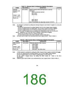
Table 79 - Interrupt Select Configuration Register Description
NAME
Interrupt
REG INDEX
DEFINITION
STATE
0x70 (R/W)
Bits[3:0] selects which interrupt level is used for
C
Request Level
Select 0
Interrupt 0.
0x00=no interrupt selected.
0x01=IRQ1
0x02=IRQ2
Default = 0x00
•
•
•
on Vcc POR or
Reset_Drv
0x0E=IRQ14
0x0F=IRQ15
Note: All interrupts are edge high (except ECP/EPP)
Note:
An Interrupt is activated by setting the Interrupt Request Level Select 0 register to a non-zero
value AND :
for the FDC logical device by setting DMAEN, bit D3 of the Digital Output Register.
for the PP logical device by setting IRQE, bit D4 of the Control Port and in addition
for the PP logical device in ECP mode by clearing serviceIntr, bit D2 of the ecr.
for the Serial Port logical device by setting any combination of bits D0-D3 in the IER
and by setting the OUT2 bit in the UART's Modem Control (MCR) Register.
for the RTC by (refer to the RTC section of this spec.)
for the KYBD by (refer to the KYBD controller section of this spec.)
IRQ pins must tri-state if not used/selected by any Logical Device. Refer to Note A.
Note:
Table 80 - DMA Channel Select Configuration Register Description
NAME
REG INDEX
DEFINITION
STATE
DMA Channel
Select
0x74 (R/W)
Bits[2:0] select the DMA Channel.
0x00=DMA0
C
0x01=DMA1
0x02=DMA2
0x03=DMA3
0x04-0x07= No DMA active
Default = 0x04
on Vcc POR or
Reset_Drv
Note:
A DMA channel is activated by setting the DMA Channel Select register to [0x00-0x03] AND :
for the FDC logical device by setting DMAEN, bit D3 of the Digital Output Register.
for the PP logical device in ECP mode by setting dmaEn, bit D3 of the ecr.
for the UART 2 logical device, by setting the DMA Enable bit. Refer to the IRCC
specification.
Note:
DMAREQ pins must tri-state if not used/selected by any Logical Device. Refer to Note A.
186

 SMSC [ SMSC CORPORATION ]