Note A. Logical Device IRQ and DMA Operation
1. IRQ and DMA Enable and Disable: Any time the IRQ or DACK for a logical block is disabled by a
register bit in that logical block, the IRQ and/or DACK must be disabled. This is in addition to
the IRQ and DACK disabled by the Configuration Registers (active bit or address not valid).
a. FDC: For the following cases, the IRQ and DACK used by the FDC are disabled (high
impedance). Will not respond to the DREQ
Digital Output Register (Base+2) bit D3 (DMAEN) set to "0".
The FDC is in power down (disabled).
b. IDE1 and IDE2: No additional conditions.
c. Serial Port 1 and 2:
Modem Control Register (MCR) Bit D2 (OUT2) - When OUT2 is a logic "0", the
serial port interrupt is forced to a high impedance state - disabled.
d. Parallel Port:
I. SPP and EPP modes: Control Port (Base+2) bit D4 (IRQE) set to "0", IRQ is
disabled (high impedance).
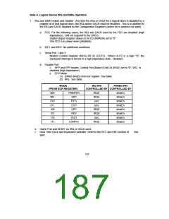
ii. ECP Mode:
(1) (DMA) dmaEn from ecr register. See table.
(2) IRQ - See table.
MODE
IRQ PIN
PDREQ PIN
(FROM ECR REGISTER)
CONTROLLED BY CONTROLLED BY
000
001
010
011
100
101
110
111
PRINTER
SPP
IRQE
IRQE
(on)
dmaEn
dmaEn
dmaEn
dmaEn
dmaEn
dmaEn
dmaEn
dmaEn
FIFO
ECP
(on)
EPP
IRQE
IRQE
(on)
RES
TEST
CONFIG
IRQE
e. Game Port and ADDR: no IRQ or DACK used.
f. Real Time Clock and Keyboard Controller: Refer to the RTC and KBD section of
spec.
this
187

 SMSC [ SMSC CORPORATION ]