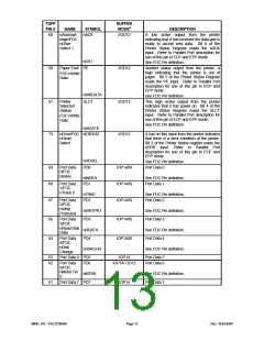
TQFP
PIN #
82,84 nRing
BUFFER
MODE6
NAME
SYMBOL
nRI1
DESCRIPTION
I
Active low Ring Indicator inputs for the serial port.
Handshake signal which notifies the UART that the
telephone ring signal is detected by the modem.
The CPU can monitor the status of nRI signal by
reading bit 6 of Modem Status Register (MSR). A
nRI signal state change from low to high after the
last MSR read will set MSR bit 2 to a 1. If bit 3 of
Interrupt Enable Register is set, the interrupt is
generated when nRI changes state. Note: Bit 6 of
MSR is the complement of nRI.
(Note1)
Indicator
nRI2
TQFP
PIN #
BUFFER
NAME
SYMBOL
MODE6
DESCRIPTION
PARALLEL PORT INTERFACE (NOTE 2)
71
nPrinter
Select
nSLCT
(OD14/OP14)/OD12 This active low output selects the printer.
This is the complement of bit 3 of the Printer
Control Register.
Input/FDC
nStep
Refer to Parallel Port description for use of
Pulse
this pin in ECP and EPP mode.
See FDC Pin definition.
(Note3)
nSTEP
nINIT
72
nInitiate
Output/
(OD14/OP14)/OD12 This output is bit 2 of the printer control
register. This is used to initiate the printer
when low.
FDC
nDirection
Control
Refer to Parallel Port description for use of
this pin in ECP and EPP mode.
(Note3)
nDIR
See FDC Pin definition.
74
nAutofeed
Output/
nAUTOFD
(OD14/OP14)/OD12 This output goes low to cause the printer to
automatically feed one line after each line is
printed.
The nAUTOFD output is the
FDC
complement of bit 1 of the Printer Control
nDensity
Select
Register.
(Note3)
Refer to Parallel Port description for use of
this pin in ECP and EPP mode.
See FDC Pin definition.
nDENSEL
nSTROBE
75
59
nStrobe
Output/
(OD14/OP14)/OD12 An active low pulse on this output is used to
strobe the printer data into the printer. The
nSTROBE output is the complement of bit 0
of the Printer Control Register.
FDC nDrive
Select 0
(Note3)
Refer to Parallel Port description for use of
this pin in ECP and EPP mode.
See FDC Pin definition.
nDS0
BUSY
Busy/
I/OD12
This is a status output from the printer, a
high indicating that the printer is not ready to
receive new data. Bit 7 of the Printer Status
Register is the complement of the BUSY
input. Refer to Parallel Port description for
use of this pin in ECP and EPP mode.
FDC
nMotor On
1
See FDC Pin definition.
nMTR1
SMSC DS – FDC37N3869
Page 12
Rev. 10/25/2000

 SMSC [ SMSC CORPORATION ]