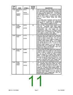
TQFP
PIN #
8
BUFFER
MODE6
NAME
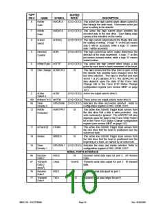
nWrite
Gate
SYMBOL
nWGATE
DESCRIPTION
(O12/ OD12) This active low high current driver allows current to
flow through the write head. It becomes active just
prior to writing to the diskette.
7
9
nWrite
Data
nWDATA
nHDSEL
(O12/ OD12) This active low high current driver provides the
encoded data to the disk drive. Each falling edge
causes a flux transition on the media.
(O12/ OD12) This high current output selects the floppy disk side
for reading or writing. A logic “1” on this pin means
side 0 will be accessed, while a logic “0” means
side 1 will be accessed.
nHead
Select
5
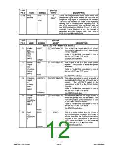
Direction
Control
nDIR
(O12/ OD12) This high current low active output determines the
direction of the head movement. A logic “1” on this
pin means outward motion, while a logic “0” means
inward motion.
6
nStep Pulse nSTEP
(O12/ OD12) This active low high current driver issues a low
pulse for each track-to-track movement of the head.
15
Disk Change nDSKCHG
IS
This input senses that the drive door is open or that
the diskette has possibly been changed since the
last drive selection. This input is inverted and read
via bit 7 of I/O address 3F7H. The nDSKCHG bit
also depends upon the state of the Force Disk
Change bits in the Force FDD Status Change
configuration register (see section CR17 on page
107).
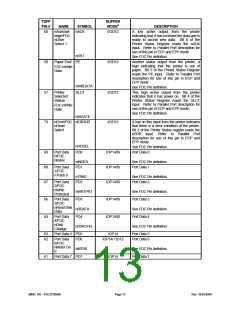
2
nDrive
nDS0
(O12/ OD12) Active low output selects drive 0.
Select 0
100
99
nMotor On 0 nMTR0
(O12/ OD12) These active low output selects motor drive 0.
Drive
DRVDEN0 (O12/ OD12) Indicates the drive and media selected. Refer to
Density 0
configuration registers CR03, CR0B, CR1F.
12
nWrite
Protected
nWRTPRT
IS
This active low Schmitt Trigger input senses from
the disk drive that a disk is write protected. Any
write command is ignored. The nWRPRT bit also
depends upon the state of the Force Write Protect
bit in the Force FDD Status Change configuration
register (see section CR17 on page 107).
11
10
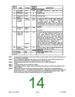
16
wTrack 00
nIndex
nTRK0
IS
IS
This active low Schmitt Trigger input senses from
the disk drive that the head is positioned over the
outermost track.
This active low Schmitt Trigger input senses from
the disk drive that the head is positioned over the
beginning of a track, as marked by an index hole.
nINDEX
Drive
DRVDEN 1 (O12/ OD12) Indicates the drive and media selected. Refer to
Density 1
configuration registers CR03, CR0B, CR1F.
SERIAL PORTS INTERFACE
86
87
Receive
Data 2
RXD2
TXD2
IS
Receiver serial data input for port 2. IR Receive
Data
Transmit
O12PD
Transmit serial data output for port 2. IR transmit
data.
Data 2
(Note5)
76
77
Receive
RXD1
TXD1
I
Receiver serial data input for port 1.
Transmit serial data output for port 1.
Data 1
Transmit
Data 1
O12
SMSC DS – FDC37N3869
Page 10
Rev. 10/25/2000

 SMSC [ SMSC CORPORATION ]