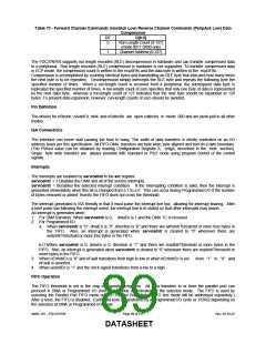
Table 70 - Forward Channel Commands (HostAck Low) Reverse Channel Commands (PeripAck Low) Data
Compression
D7
D[6:0]
0
Run-Length Count (0-127)
(mode 0011 0X00 only)
Channel Address (0-127)
1
The FDC37N769 supports run length encoded (RLE) decompression in hardware and can transfer compressed data
to a peripheral. Run length encoded (RLE) compression in hardware is not supported. To transfer compressed data
in ECP mode, the compression count is written to the ecpAFifo and the data byte is written to the ecpDFifo.
Compression is accomplished by counting identical bytes and transmitting an RLE byte that indicates how many times
the next byte is to be repeated. Decompression simply intercepts the RLE byte and repeats the following byte the
specified number of times. When a run-length count is received from a peripheral, the subsequent data byte is
replicated the specified number of times. A run-length count of zero specifies that only one byte of data is represented
by the next data byte, whereas a run-length count of 127 indicates that the next byte should be expanded to 128
bytes. To prevent data expansion, however, run-length counts of zero should be avoided.
Pin Definition
The drivers for nStrobe, nAutoFd, nInit and nSelectIn are open-collector in mode 000 and are push-pull in all other
modes.
ISA Connections
The interface can never stall causing the host to hang. The width of data transfers is strictly controlled on an I/O
address basis per this specification. All FIFO-DMA transfers are byte wide, byte aligned and end on a byte boundary.
(The PWord value can be obtained by reading Configuration Register A, cnfgA, described in the next section).
Single byte wide transfers are always possible with standard or PS/2 mode using program control of the control
signals.
Interrupts
The interrupts are enabled by serviceIntr in the ecr register.
serviceIntr = 1 Disables the DMA and all of the service interrupts.
serviceIntr = 0Enables the selected interrupt condition. If the interrupting condition is valid, then the interrupt is
generated immediately when this bit is changed from a 1 to a 0. This can occur during Programmed I/O if the number
of bytes removed or added from/to the FIFO does not cross the threshold.
The interrupt generated is ISA friendly in that it must pulse the interrupt line low, allowing for interrupt sharing. After
a brief pulse low following the interrupt event, the interrupt line is tri-stated so that other interrupts may assert.
An interrupt is generated when:
1. For DMA transfers: When serviceIntr is 0, dmaEn is 1 and the DMA TC is received.
2. For Programmed I/O:
a. When serviceIntr is “0”, dmaEn is “0”, direction is “0” and there are writeIntrThreshold or more free bytes in
the FIFO. Also, an interrupt is generated when serviceIntr is cleared to “0” whenever there are
writeIntrThreshold or more free bytes in the FIFO.
b.(1)When serviceIntr is 0, dmaEn is 0, direction is “1” and there are readIntrThreshold or more bytes in the
FIFO. Also, an interrupt is generated when serviceIntr is cleared to “0” whenever there are readIntrThreshold or
more bytes in the FIFO.
3. When nErrIntrEn is “0” and nFault transitions from high to low or when nErrIntrEn is set
nFault is asserted.
from “1” to “0” and
4. When ackIntEn is “1” and the nAck signal transitions from a low to a high.
FIFO Operation
The FIFO threshold is set in the chip configuration registers. All data transfers to or from the parallel port can
proceed in DMA or Programmed I/O (non-DMA) mode as indicated by the selected mode. The FIFO is used by
selecting the Parallel Port FIFO mode or ECP Parallel Port Mode. (FIFO test mode will be addressed separately.)
After a reset, the FIFO is disabled. Each data byte is transferred by a Programmed I/O cycle or PDRQ depending on
the selection of DMA or Programmed I/O mode.
SMSC DS – FDC37N769
Page 89 of 137
Rev. 02-16-07
DATASHEET

 SMSC [ SMSC CORPORATION ]