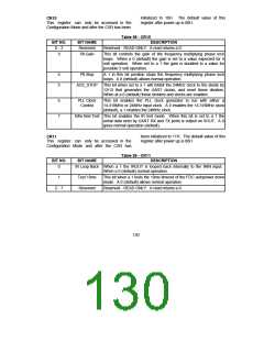
can be set to 48 locations, on 16 byte
boundaries from 100H-3F0H. To disable this
decode, set ADR9 and ADR8 to zero.
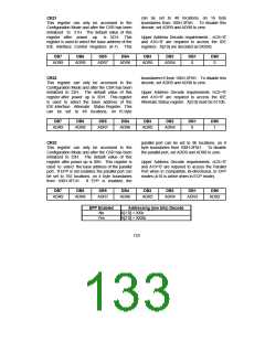
CR21
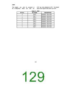
This register can only be accessed in the
Configuration Mode and after the CSR has been
initialized to 21H. The default value of this
register after power up
register is used to select the base address of the
IDE Interface Control Registers (0-7). This
is 3CH. This
Upper Address Decode requirements : nCS='0'
and A10='0' are required to access the IDE
registers. A[3:0] are decoded as 0XXXb.
DB7
DB6
DB5
DB4
DB3
DB2
DB1
DB0
ADR9
ADR8
ADR7
ADR6
ADR5
ADR4
0
0
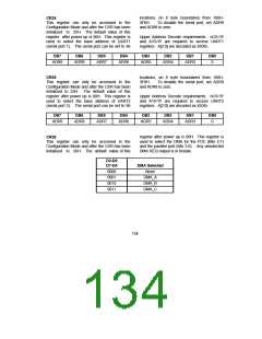
boundaries+6 from 106H-3F6H. To disable this
decode, set ADR9 and ADR8 to zero.
CR22
This register can only be accessed in the
Configuration Mode and after the CSR has been
initialized to 22H. The default value of this
register after power up is 3DH. This register
is used to select the base address of the
IDE Interface Alternate Status Register. This
can be set to 48 locations, on 16 byte
Upper Address Decode requirements: nCS='0'
and A10='0' are required to access the IDE
Alternate Status register. A[3:0] must be 0110b.
DB7
DB6
DB5
DB4
DB3
DB2
DB1
DB0
ADR9
ADR8
ADR7
ADR6
ADR5
ADR4
0
1
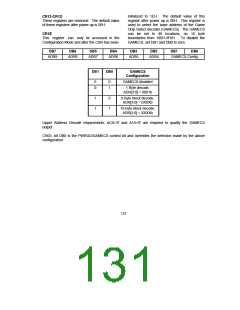
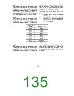
parallel port can be set to 96 locations, on 8
byte boundaries from 100H-3F8H. To disable
the parallel port, set ADR9 and ADR8 to zero.
CR23
This register can only be accessed in the
Configuration Mode and after the CSR has been
initialized to 23H. The default value of this
register after power up is 00H. This register is
used to select the base address of the parallel
port. If EPP is not enabled, the parallel port can
be set to 192 locations, on 4 byte boundaries
Upper Address Decode requirements: nCS='0'
and A10='0' are required to access the Parallel
Port when in Compatible, Bi-directional, or EPP
modes (A10 is active when in ECP mode).
from 100H-3FCH.
If EPP is enabled, the
DB7
DB6
ADR8
DB5
DB4
DB3
DB2
DB1
DB0
ADR9
ADR7
ADR6
ADR5
ADR4
ADR3
ADR2
EPP Enabled
Addressing (low bits) Decode
A[1:0] = XXb
No
Yes
A[2:0] = XXXb
133

 SMSC [ SMSC CORPORATION ]