function is selected for the GPIO pin, then the
bits that control input/output, polarity and open
collector/push-pull have no effect on the function
of the pin. However, the polarity bit does affect
the value of the GP bit (i.e., register GP1, bit 2
for GP12).
EITHER EDGE TRIGGERED INTERRUPTS
Four GPIO pins are implemented that allow an
interrupt to be generated on both a high-to-low
and a low-to-high edge transition, instead of one
or the other as selected by the polarity bit.
An interrupt occurs if the status bit is set and the
interrupt is enabled. The status bits indicate
which of the EETI interrupts transitioned. These
status bits are located in the MSC_STS register.
The status is valid whether or not the interrupt is
enabled and whether or not the EETI function is
selected for the pin.
The either edge triggered interrupts function as
follows: Selecting the Either Edge Triggered
Interrupt (EETI) function for these GPIO pins is
applicable when the combined interrupt is
enabled for the GPIO pin (GPINT1 for GP10-
GP17, and GPINT2 for GP50-GP54 and GP60-
GP67). Otherwise, selection of the EETI function
will produce no function for the pin. If the EETI
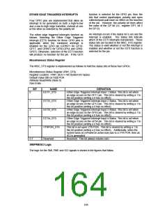
Miscellaneous Status Register
The MSC_STS register is implemented as follows to hold the status bits of these four GPIOs.
Miscellaneous Status Register (PM1_STS)
Register Location: <PM1_BLK>+16h System I/O Space
Default Value:00h on Vbat POR
Attribute:Read/Write (Note 0)
Size:8-bits
BIT
NAME
DEFINITION
0
1
2
3
4
EETI1_STS
Either Edge Triggered Interrupt Input 1 Status. This bit is set when
an edge occurs on the GP11 pin. This bit is cleared by writing a 1 to
this bit position (writing a 0 has no effect).
Either Edge Triggered Interrupt Input 2 Status. This bit is set when
an edge occurs on the GP12 pin. This bit is cleared by writing a 1 to
this bit position (writing a 0 has no effect).
Either Edge Triggered Interrupt Input 3 Status. This bit is set when
an edge occurs on the GP53 pin. This bit is cleared by writing a 1 to
this bit position (writing a 0 has no effect).
Either Edge Triggered Interrupt Input 4 Status. This bit is set when
an edge occurs on the GP54 pin. This bit is cleared by writing a 1 to
this bit position (writing a 0 has no effect).
EETI2_STS
EETI3_STS
EETI4_STS
VTRPOR_STS
This bit is set upon VTR POR. This bit is cleared by writing a 1 to
this bit position (writing a 0 has no effect). Additionally, when the
system turns on (nPowerOn active low) due to a VTR POR, then an
SCI is generated.
5-7
Reserved
Reserved. This bit always returns zero.
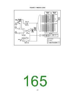
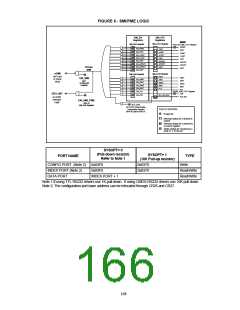
SMI/PME/SCI Logic
The logic for the SMI, PME and SCI signals is shown in the figures that follow.
166

 SMSC [ SMSC CORPORATION ]