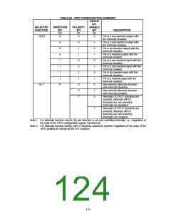
TABLE 55 - GPIO CONFIGURATION SUMMARY
GROUP
INT.
SELECTED
FUNCTION
DIRECTION
POLARITY
ENABLE
BIT
B0
0
BIT
B1
0
BIT
B5
0
DESCRIPTION
GPIO
Pin is a non-inverted output with
the Interrupt disabled.
0
0
0
1
1
0
0
1
1
0
0
12
1
0
1
0
1
0
1
0
1
0
Pin is a non-inverted output with
the Interrupt enabled.
Pin is an inverted output with the
Interrupt disabled.
Pin is a inverted output with the
Interrupt enabled.
Pin is a non-inverted input with the
Interrupt disabled.
Pin is a non-inverted input with the
Interrupt enabled.
Pin is an inverted input with the
Interrupt disabled.
Pin is a inverted input with the
Interrupt enabled.
Non-inverted alternate function
with Interrupt disabled.
0
1
1
1
1
ALT.
X1
Non-inverted alternate function
with Interrupt enabled.
Alternate OUTPUT functions are
inverted, Alternate INPUT
functions are non-inverted;
Interrupts are disabled.
1
Alternate OUTPUT functions are
inverted, Alternate INPUT
functions are non-inverted;
Interrupts are enabled.
Note 1. For alternate function selects, the pin direction is set and controlled internally; i.e., regardless of
the state of the GPIO configuration register Direction bit.
Note 2. For alternate function selects, INPUT functions cannot be inverted, regardless of the state of the
GPIO polarity bit, except for the EETI function.
126

 SMSC [ SMSC CORPORATION ]