Fan Control Device with Hardware Monitoring and Acoustic Noise Reduction Features
Datasheet
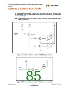
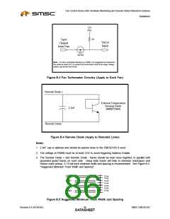
Appendix B Example Fan Circuits
The following figures show examples of circuitry on the board for the PWM outputs, tachometer inputs,
and remote diodes. Figure B.1 shows how the part can be used to control four fans by connecting two
fans to one PWM output.
Note: These examples represent the minimum required components. Some designs may require
additional components.
12
V
3.3V
3.3V
1k
2.2k
PWMx
MMBT3904
M
Fan1
10
MMBT2222
MMBT2222
Empty
Empty
M
10
Fan2
Figure B.1 Fan Drive Circuitry (Apply to PWM Driving Two Fans)
3.3V
12V
Fan
470
M
PWMx
0
MMBT2222
Empty
Figure B.2 Fan Drive Circuitry (Apply to PWM Driving One Fan)
SMSC EMC6D102
Revision 0.4 (04-05-05)
DATA8S5HEET

 SMSC [ SMSC CORPORATION ]