Fan Control Device with Hardware Monitoring and Acoustic Noise Reduction Features
Datasheet
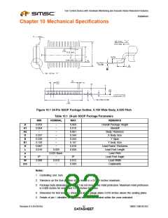
Chapter 10 Mechanical Specifications
Figure 10.1 24-Pin SSOP Package Outline, 0.150 Wide Body, 0.025 Pitch
Table 10.1 24-pin SSOP Package Parameters
MIN
NOMINAL
MAX
REMARKS
A
A1
A2
D
E
E1
H
L
e
è
W
ccc
0.053
0.004
~
0.337
0.228
0.150
0.007
0.016
~
~
~
~
~
~
~
0.069
0.010
0.061
0.344
0.244
0.157
0.010
0.050
Overall Package Height
Standoff
Body Thickness
X Body Size
Y Span
Y body Size
Lead Frame Thickness
Lead Foot Length
Lead Pitch
0.025
0.025 Basic
0o
0.008
~
~
0.010
~
8o
0.012
0.004
Lead Foot Angle
Lead Width
Coplanarity
Notes:
1. Controlling Unit: inch.
2. Tolerance on the true position of the leads is ± 0.0035 inches maximum.
3. Package body dimensions D and E1 do not include the mold protrusion. Maximum mold protrusion
is 0.006 inches for ends, and 0.010 inches for sides.
4. Dimension for foot length L measured at the gauge plane 0.010 inches above the seating plane.
5. Details of pin 1 identifier are optional but must be located within the zone indicated.
Revision 0.4 (04-05-05)
SMSC EMC6D102
DATA8S2HEET

 SMSC [ SMSC CORPORATION ]