Fan Control Device with Hardware Monitoring and Acoustic Noise Reduction Features
Datasheet
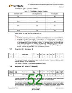
The Voltage Reading registers reflect the current voltage of the EMC6D102 voltage monitoring inputs.
Voltages are presented in the registers at ¾ full scale for the nominal voltage, meaning that at nominal
voltage, each register will read C0h.
Table 7.2 Voltage vs. Register Reading
REGISTER
READING AT
NOMINAL
REGISTER
READING AT
MAXIMUM
REGISTER
NOMINAL
MAXIMUM
VOLTAGE
MINIMUM
READING AT
INPUT VOLTAGE
VOLTAGE
VOLTAGE
VOLTAGE MINIMUM VOLTAGE
+2.5V
Vccp
VCC
+5V
2.5V
2.25V
3.3V
5.0V
12.0V
C0h
C0h
C0h
C0h
C0h
3.32V
3.00V
4.38V
6.64V
16.00V
FFh
FFh
FFh
FFh
FFh
0V
0V
0V
0V
0V
00h
00h
00h
00h
00h
+12V
The Voltage Reading registers will be updated automatically by the EMC6D102 Chip with a minimum
frequency of 4Hz. These registers are read only – a write to these registers has no effect.
7.2.4
Registers 25-27h: Temperature Reading
Register
Address
Read/
Write
Bit 7
Bit 0
Default
Value
Register Name
Bit 6
Bit 5
Bit 4
Bit 3
Bit 2
Bit 1
(MSb)
(LSb)
25h
26h
27h
R
R
R
Remote Diode 1 Temp Reading
Internal Temp Reading
7
7
7
6
6
6
5
5
5
4
4
4
3
3
3
2
2
2
1
1
1
0
0
0
N/A
N/A
N/A
Remote Diode 2 Temp Reading
The Temperature Reading registers reflect the current temperatures of the internal and remote diodes.
Remote Diode 1 Temp Reading register reports the temperature measured by the Remote1- and
Remote1+ pins, Remote Diode 2 Temp Reading register reports the temperature measured by the
Remote2- and Remote2+ pins, and the Internal Temp Reading register reports the temperature
measured by the internal (ambient) temperature sensor. Current temperatures are represented as 8
bit, 2’s complement, signed numbers in Celsius, as shown below in Table 7.3. The Temperature
Reading register will return a value of 80h if the remote diode pins are not implemented by the board
designer or are not functioning properly (this corresponds to the diode fault interrupt status bits). The
Temperature Reading registers will be updated automatically by the EMC6D102 Chip with a minimum
frequency of 4Hz.
Note: These registers are read only – a write to these registers has no effect.
Each of the temperature reading registers are mapped to a zone. Each PWM may be programmed to
operate in the auto fan control operating mode by associating a PWM with one or more zones. The
following is a list of the zone associations.
■
■
■
Zone 1 is controlled by Remote Diode 1 Temp Reading
Zone 2 is controlled by Internal Temp Reading (Ambient Temperature Sensor)
Zone 3 is controlled by Remote Diode 2 Temp Reading
SMSC EMC6D102
Revision 0.4 (04-05-05)
DATA4S9HEET

 SMSC [ SMSC CORPORATION ]