RPM-Based PWM Fan Controller
Datasheet
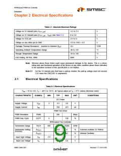
Chapter 2 Electrical Specifications
Table 2.1 Absolute Maximum Ratings
Voltage on 5V tolerant pins (V5VT_pin
)
-0.3 to 5.5
0 to 3.6
V
Voltage on 5V tolerant pins (|V5VT_pin - VDD|) (see Note 2.1)
Voltage on VDD pin
V
-0.3 to 4
-0.3 to VDD + 0.3
141
V
Voltage on any other pin to GND
V
Package Thermal Resistance - Junction to Ambient (θJA
Operating Ambient Temperature Range
Storage Temperature Range
)
°C/W
°C
°C
V
-40 to 125
-55 to 150
2000
ESD Rating, All Pins, HBM
Note: Stresses above those listed could cause permanent damage to the device. This is a stress
rating only and functional operation of the device at any other condition above those indicated
in the operation sections of this specification is not implied.
Note 2.1 For the 5V tolerant pins that have a pull-up resistor, the pull-up voltage must not exceed
3.6V when the EMC2301 is unpowered.
2.1
Electrical Specifications
Table 2.2 Electrical Specifications
VDD = 3V to 3.6V, TA = -40°C to 125°C, all Typical values at TA = 27°C unless otherwise noted.
CHARACTERISTIC
SYMBOL
MIN
TYP
MAX
UNIT
CONDITIONS
DC Power
3.3
Supply Voltage
Supply Current
VDD
IDD
3
3.6
V
350
475
uA
PWM Fan Driver
256
PWM Resolution
PWM Duty Cycle
PWM
Steps
%
DUTY
0
100
RPM-based Fan Controller
Tachometer Range
TACH
ΔTACH
ΔTACH
VIH
480
16000
±1
RPM
%
Tachometer Setting
Accuracy
±0.5
±1
External oscillator 32.768kHz
Internal Oscillator
±2
%
Input High Voltage
Input Low Voltage
2.0
V
VIL
0.8
V
SMSC EMC2301
9
Revision 1.1 (10-12-09)
DATASHEET

 SMSC [ SMSC CORPORATION ]