RPM-Based PWM Fan Controller
Datasheet
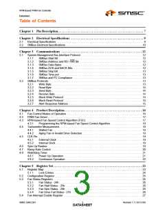
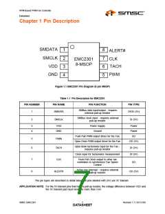
Chapter 1 Pin Description
SMDATA
SMCLK
VDD
1
2
3
4
8
7
6
5
ALERT#
CLK
EMC2301
8-MSOP
TACH
PWM
GND
Figure 1.1 EMC2301 Pin Diagram (8 pin MSOP)
Table 1.1 Pin Description for EMC2301
PIN NUMBER
PIN NAME
PIN FUNCTION
PIN TYPE
SMBus data input/output - requires
external pull-up resistor
1
SMDATA
DIOD (5V)
SMBus clock input - requires external
pull-up resistor
2
SMCLK
DI (5V)
3
4
VDD
GND
Power Supply
Ground
Power
Power
DO
Push-Pull PWM output driver for the Fan
Open Drain PWM output driver for the Fan
5
6
PWM
TACH
OD (5V)
Open drain tachometer input for the Fan -
requires pull-up resistor
DI (5V)
DI (5V)
Clock input for tachometer measurement
Push-Pull Clock output to other fan
controllers to synchronize Fan Speed
Control
7
8
CLK
DO
Active low interrupt - requires external
pull-up resistor.
ALERT#
OD (5V)
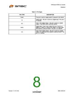
The pin types are described in detail below. All pins labeled with (5V) are 5V tolerant.
APPLICATION NOTE: For the 5V tolerant pins that have a pull-up resistor, the voltage difference between VDD and
the 5V tolerant pad must never be more than 3.6V.
SMSC EMC2301
7
Revision 1.1 (10-12-09)
DATASHEET

 SMSC [ SMSC CORPORATION ]