RPM-Based PWM Fan Controller
Datasheet
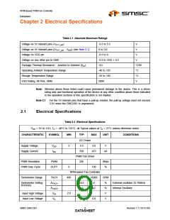
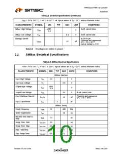
Table 2.2 Electrical Specifications (continued)
VDD = 3V to 3.6V, TA = -40°C to 125°C, all Typical values at TA = 27°C unless otherwise noted.
CHARACTERISTIC
SYMBOL
MIN
TYP
MAX
UNIT
CONDITIONS
8 mA current drive
Output High Voltage
VDD -
0.4
VOH
VOL
V
V
Output Low Voltage
Leakage current
0.4
±5
8 mA current sink
ALERT# pin
Powered and unpowered
0°C < TA < 85°C
ILEAK
uA
pull-up voltage < 3.6V
Note 2.2 All voltages are relative to ground.
2.2
SMBus Electrical Specifications
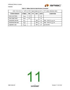
Table 2.3 SMBus Electrical Specifications
VDD= 3V to 3.6V, TA = -40°C to 125°C Typical values are at TA = 27°C unless otherwise noted.
CHARACTERISTIC
SYMBOL
MIN
TYP
MAX
UNITS
CONDITIONS
SMBus Interface
Input High Voltage
Input Low Voltage
Output High Voltage
VIH
VIL
2.0
V
V
0.8
VDD
- 0.4
VOH
VOL
V
V
Output Low Voltage
0.4
±5
4 mA current sink
Input High/Low Current
Powered and unpowered
0°C < TA < 85°C
IIH / IIL
CIN
uA
pF
Input Capacitance
5
SMBus Timing
Clock Frequency
fSMB
tSP
10
400
50
kHz
ns
Spike Suppression
Bus free time Start to
Stop
tBUF
1.3
us
Setup Time: Start
Setup Time: Stop
Data Hold Time
Data Setup Time
tSU:STA
tSU:STP
tHD:DAT
tSU:DAT
0.6
0.6
0.6
0.6
us
us
us
us
6
72
Revision 1.1 (10-12-09)
SMSC EMC2301
DATA1S0HEET

 SMSC [ SMSC CORPORATION ]