RPM-Based PWM Fan Controller
Datasheet
3.1.5
SMBus Stop Bit
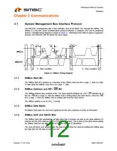
The SMBus Stop bit is defined as a transition of the SMBus Data line from a logic ‘0’ state to a logic
‘1’ state while the SMBus clock line is in a logic ‘1’ state. When the EMC2301 detects an SMBus Stop
bit has been communicating with the SMBus protocol, it will reset its client interface and prepare to
receive further communications.
3.1.6
SMBus Time-out
The EMC2301 includes an SMBus timeout feature. Following a 30ms period of inactivity on the
SMBus, the device will time-out and reset the SMBus interface.
The SMBus timeout feature is disabled by default and can be enabled via clearing the DIS_TO bit in
the Configuration register (20h).
2
3.1.7
SMBus and I C Compliance
The major difference between SMBus and I2C devices is highlighted here. For complete compliance
information refer to the SMBus 2.0 specification.
1. Minimum frequency for SMBus communications is 10kHz (I2C has no minimum frequency).
2. The slave protocol will reset if the clock is held low for longer than 30ms (I2C has no timeout).
3. The slave protocol will reset if both the clock and data lines are held high for longer than 150us.
4. I2C devices do not support the Alert Response Address functionality (which is optional for SMBus).
5. The Block Read and Block Write protocols are only compliant with I2C data formatting. They do
not support SMBus formatting for Block Read and Block Write protocols.
3.2
SMBus Protocols
The EMC2301 is SMBus 2.0 compatible and supports Send Byte, Read Byte, Receive Byte and Write
Byte as valid protocols as shown below. It will respond to the Alert Response Address protocol but is
not in full compliance.
All of the below protocols use the convention in Table 3.1. When reading the protocol blocks, the value
of YYYY_YYYb should be replaced with the respective SMBus addresses.
Table 3.1 Protocol Format
DATA SENT
TO DEVICE
DATA SENT TO
THE HOST
# of bits sent
# of bits sent
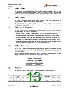
3.2.1
Write Byte
The Write Byte is used to write one byte of data to the registers as shown below Table 3.2.
Table 3.2 Write Byte Protocol
SLAVE
ADDRESS
REGISTER
ADDRESS
REGISTER
DATA
START
1 -> 0
WR
ACK
ACK
ACK
STOP
YYYY_YYYb
0
0
XXh
0
XXh
0
0 -> 1
SMSC EMC2301
Revision 1.1 (10-12-09)
DATA1S3HEET

 SMSC [ SMSC CORPORATION ]