RPM-Based Fan Controller with HW Thermal Shutdown
Datasheet
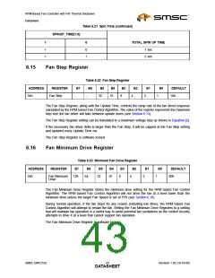
Table 6.21 Spin Time (continued)
SPINUP_TIME[1:0]
1
0
TOTAL SPIN UP TIME
1
1
0
1
1 sec
2 sec
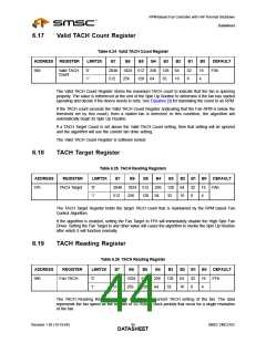
6.15
Fan Step Register
Table 6.22 Fan Step Register
B6 B5 B4 B3
32 16
ADDRESS
REGISTER
B7
B2
B1
B0
DEFAULT
10h
54h
Fan Step
-
-
8
4
2
1
The Fan Step Register, along with the Update Time, controls the ramp rate of the fan driver response
calculated by the RPM based Fan Control Algorithm. The value of the register represents the maximum
step size the fan driver will take between update times (see Section 6.13).
The Fan Step Register setting can be translated to a maximum voltage step as shown in Equation [2].
If the necessary fan driver delta is larger than the Fan Step, it will be capped at the Fan Step setting
and updated every Update Time ms.
The Fan Step Register is software locked.
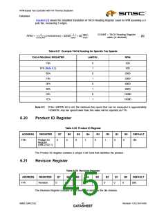
6.16
Fan Minimum Drive Register
Table 6.23 Minimum Fan Drive Register
ADDRESS
REGISTER
B7
B6
64
B5
32
B4
16
B3
B2
B1
B0
DEFAULT
80h
55h
Fan Minimum
Drive
128
8
4
2
1
The Fan Minimum Drive Register stores the minimum drive setting for the RPM based Fan Control
Algorithm. The RPM based Fan Control Algorithm will not drive the fan at a level lower than the
minimum drive unless the target Fan Speed is set at FFh (see Section 6.18)
During normal operation, if the fan stops for any reason (including low drive), the RPM based Fan
Control Algorithm will attempt to restart the fan. Setting the Fan Minimum Drive Registers to a setting
that will maintain fan operation is a useful way to avoid potential fan oscillations as the control circuitry
attempts to drive it at a level that cannot support fan operation.
The Fan Minimum Drive Register is software locked.
SMSC EMC2102
Revision 1.95 (10-19-06)
DATA4S3HEET

 SMSC [ SMSC CORPORATION ]