Legacy-Free Keyboard/Embedded Controller with SPI and LPC Docking Interface
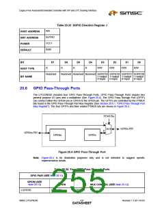
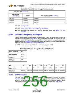
Table 20.34 Four GPIO Pass-Through Ports (continued)
GPIO PAIR (SEE Note 20.11)
GPIOM (SEE
Note 20.13)
GPION
LGPIO61
MUX CONTROL (SEE Note 20.12)
LGPIO51
PTMUX2
PTMUX3
PTMUX4
LGPIO52
LGPIO53
LGPIO62
LGPIO63
Note 20.11 See Figure 20.4
Note 20.12 Section 20.6.1, "GPIO Pass-Through Port Mux Register"
Note 20.13 These pins can generate 8051 interrupts and wake events. See Section 7.9, "8051
Interrupts".
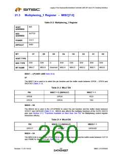
20.6.1 GPIO Pass-Through Port Mux Register
The GPIO Pass-Through Port Mux Register contains the four PTMUX bits that are used to control the
GPIO Pass-Through Ports (See Table 20.35). When a PTMUX is “0” (default), the pass-through mode
is disabled and the GPIO pins function normally. When a PTMUX bit is “1”, the pass-through mode is
enabled, GPIOn (See Figure 20.4) is disconnected and the signal at the GPIOm pin appears unmodified
at the GPIOn pin (See Section 20.6.2, "GPTP Multiplexer").
The GPTM register is powered by VCC1 and is controlled solely by the 8051.
Table 20.35 GPIO Pass-Through Port Mux (GPTM) Register
N/A
HOST ADDRESS
8051 ADDRESS
POWER
0x7F85
VCC1
0x00
DEFAULT
BIT
D7
D6
D5
D4
D3
R/W
D2
R/W
D1
R/W
D0
R/W
R
R
R
R
HOST TYPE
BIT NAME
Reserved
Reserved Reserved Reserved PTMUX4 PTMUX3 PTMUX2 PTMUX1
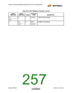
20.6.2 GPTP Multiplexer
The GPIO Pass-Through Port Multiplexer determines connectivity for GPIOn pins as shown in
Figure 20.4. GPIOn pins can be either an input or and output depending on the state of the PTMUX bit
and the GPIOn direction register. In Pass-Through mode, GPIOn pins are always an output. In Normal
mode, the GPIOn pins direction depends upon the GPIOn Direction Register (See Table 20.36).
Revision 1.1 (01-14-03)
238
SMSC LPC47N350
DATASHEET

 SMSC [ SMSC CORPORATION ]