ST7781
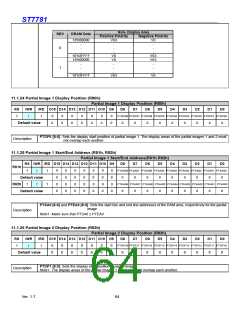
Non- Display Area
REV
DRAM Data
Positive Polarity
Negative Polarity
18’h00000
V63
V0
.
.
.
0
.
.
.
.
.
V0
V0
.
.
18’h3FFFF
18’h00000
V63
V63
.
.
.
.
1
.
.
.
.
18’h3FFFF
V63
V0
11.1.24 Partial Image 1 Display Position (R80h)
Partial Image 1 Display Position (R80h)
/RD D15 D14 D13 D12 D11 D10 D9 D8 D7 D6 D5
RS
/WR
D4
D3
D2
D1
D0
PTDP08 PTDP07 PTDP06 PTDP05 PTDP04 PTDP03 PTDP02 PTDP01 PTDP00
0
0
0
0
0
0
0
0
0
0
0
0
0
0
1
↑
1
0
0
0
0
0
0
0
0
0
Default value
PTDP0 [8:0]: Sets the display start position of partial image 1. The display areas of the partial images 1 and 2 must
Description
not overlap each another.
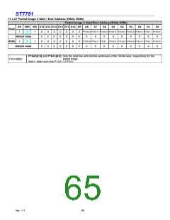
11.1.25 Partial Image 1 Start/End Address (R81h, R82h)
Partial Image 1 Start/End Address(R81h,R82h)
RS /WR /RD D15 D14 D13 D12 D11 D10 D9 D8 D7 D6 D5
D4
D3
D2
D1
D0
R81h
PTSA08 PTSA07 PTSA06 PTSA05 PTSA04 PTSA03 PTSA02 PTSA01 PTSA00
0
0
0
0
0
0
0
0
0
0
0
0
0
0
0
0
0
0
0
0
0
0
0
0
0
0
0
0
1
↑
1
0
0
0
0
0
0
0
0
0
Default value
R82h
Default value
PTEA08 PTEA07 PTEA06 PTEA05 PTEA04 PTEA03 PTEA02 PTEA01 PTEA00
1
↑
1
0
0
0
0
0
0
0
0
0
PTSA0 [8:0] and PTEA0 [8:0]: Sets the start line and end line addresses of the RAM area, respectively for the partial
image
Description
Note1: Make sure that PTSA0 ≤ PTEA0.
11.1.26 Partial Image 2 Display Position (R83h)
Partial Image 2 Display Position (R83h)
/RD D15 D14 D13 D12 D11 D10 D9 D8 D7 D6 D5
RS
/WR
D4
D3
D2
D1
D0
PTDP18 PTDP17 PTDP16 PTDP15 PTDP14 PTDP13 PTDP12 PTDP11 PTDP10
1
↑
1
0
0
0
0
0
0
0
0
0
0
0
0
0
0
Default value
0
0
0
0
0
0
0
0
0
PTDP1 [8:0]: Sets the display start position of partial image
Note1. The display areas of the partial images 1 and 2 must not overlap each another.
Description
Ver. 1.7
64

 SITRONIX [ SITRONIX TECHNOLOGY CO., LTD. ]