ST7781
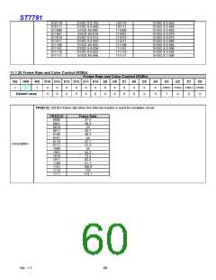
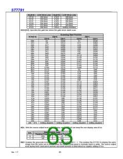
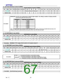
NL[5:0] LCD Drive Line NL[5:0] LCD Drive Line
6’h1D
6’h1E
6’h1F
6’h20
6’h21
6’h22
240 lines
248 lines
256 lines
264 lines
272 lines
280 lines
6’h23
6’h24
6’h25
6’h26
6’h27
Others
288 lines
296 lines
304 lines
312 lines
320 lines
Setting inhibited
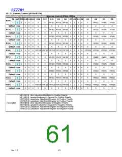
SCN [5:0]: Specifies the gate line where the gate driver starts scan.
Scanning Start Position
SCN[5:0]
SM=0
SM=1
GS=0
G1
G9
G17
G25
G33
G41
G49
G57
G65
G73
G81
G89
GS=1
G320
G312
G304
G296
G288
G280
G272
G264
G256
G248
G240
G232
G224
G216
G208
G200
G192
G184
G176
G168
G152
G152
G144
G136
G128
G120
G112
G104
G96
GS=0
G1
G17
G33
G49
G65
G81
G97
G113
G129
G145
G161
G177
G193
G209
G2
G18
G34
G50
G66
GS=1
G320
G304
G288
G272
G265
G240
G224
G208
G192
G176
G160
G144
G128
G112
G96
00h
01h
02h
03h
04h
05h
06h
07h
08h
09h
0Ah
0Bh
0Ch
0Dh
0Eh
0Fh
10h
11h
12h
13h
14h
15h
16h
17h
18h
19h
1Ah
1Bh
1Ch
1Dh
1Eh
1Fh
20h
21h
22h
23h
24h
25h
26h
27h
28h ~ 3Fh
G97
G105
G113
G121
G129
G137
G145
G153
G161
G169
G177
G185
G193
G201
G209
G217
G225
G233
G241
G249
G257
G265
G273
G281
G289
G297
G305
G313
G80
G64
G48
G32
G82
G16
G114
G114
G130
G146
G162
G178
G194
G114
G130
G146
G162
G178
G194
G210
G226
G242
G258
G274
G290
G30
G303
G303
G287
G271
G255
G239
G223
G207
G191
G175
G159
G143
G127
G111
G95
G88
G80
G72
G64
G56
G48
G40
G32
G79
G63
G47
G31
G24
G16
G8
G15
Setting disabled
Setting disabled
Setting disabled
Setting disabled
NDL: Sets the source output level in non display area. NDL bit can keep the non-display area lit on.
Non- Display Area
NDL
Positive Polarity
Negative Polarity
0
1
V63
V0
V0
V63
REV: Enables the grayscale inversion of the image by setting REV = 1. This enables the ST7781 to display the same
image from the same set of data whether the liquid crystal panel is normally black or white. The source output
level during front, back porch periods and blank periods is determined by register setting (PTS).
Ver. 1.7
63

 SITRONIX [ SITRONIX TECHNOLOGY CO., LTD. ]