ST7781
9.2 8080-Series MCU Write Cycle Sequence
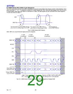
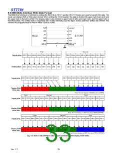
The write cycle means that the host writes information (command or/and data) to the display module via the interface. Each
write cycle (/WR “1” - “0” - “1” sequence) consists of 3 control signals (RS, /RD, /WR) and data signals (DB17:0]). RS bit is
a control signal, which tells if the data is a command or a data. The data signals are the command if the control signal is
“0” and vice versa it is data “1”.
Fig. 9.2 8080-Series /WR Protocol
Note: /WR is an unsynchronized signal (It can be stopped).
-
1 byte
2- byte
N- byte
Command
Command
Command
DB[17:0]
RESET
S
CMD
CMD
PA1
CMD
PA
1
PAN-2
PAN-1
P
“ 1 ”
/CS
RS
“ 1 ”
/RD
/WR
S
S
CMD
CMD
CMD
PA1
PA1
CMD
CMD
PA
PAN-2
PAN-1
P
P
1
DB[17:0]
Host DB[17:0]
(Host to LCD)
CMD
Hi-Z
PA
1
PAN-2
PAN-1
Driver DB[17:0]
(LCD to Host)
Signals on DB[17:0],RS,nWR,nRD
pins during nCS=1 are ignored
CMD: Write Command Code
PA: Parameter or Display Data
Fig. 9.2.1 8080-Series Parallel Bus Protocol, Write to Register or Display RAM
Ver. 1.7
29

 SITRONIX [ SITRONIX TECHNOLOGY CO., LTD. ]