ST7781
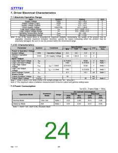
9. 8080 - Series MCU Parallel Interface
9.1 General Description
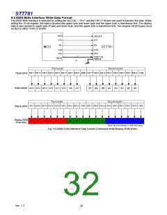
The MCU can use on of following interfaces: 11-lines with 8-bit parallel interface, 12-lines with 9-bit parallel interface,
19-lines with 16-bit parallel interface or 21-lines with 18-bit parallel interface. The chip-select /CS (active low)
enables/disables the parallel interface. RESET (active low) is an external reset signal to reset chip. /WR is the parallel data
write, /RD is the parallel data read and DB[17:0] is parallel data.
The LCD driver reads the data at the rising edge of /WR signal.Input The RS is the data/command flag. When RS=’1’, DB
[17:0] bits are either display data or command parameters. When RS =’0’, DB [17:0] bits are commands.
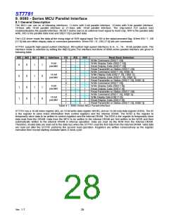
ST7781 supports high-speed system interfaces: i80-system high-speed interfaces to 8-, 9-, 16-, 18-bit parallel ports. The
interface mode is selected by setting the IM[3:0] pins.The interface functions of 8080-series parallel interface are given in
following table.
IM3 IM2 IM1 IM0
Interface
RS
0
1
1
1
0
1
1
1
0
1
1
1
0
1
1
1
/RD
1
1
↑
/WR
↑
↑
1
1
↑
Read Back Selection
Write Command (DB[17:10])
Write Display Data (DB[17:10])
8-bit
parallel
0
0
1
1
0
0
0
0
1
1
1
1
1
0
1
0
Read Display Data (DB[17:10])
↑
Read Parameter or Status (DB[17:10])
Write Command (DB[17:10], DB[8:1])
Write Display Data (DB[17:10], DB[8:1])
Read Display Data (DB[17:10], DB[8:1])
Read Parameter or Status (DB[17:10], DB[8:1])
Write Command (DB[17:10])
Write Display Data (DB[17:9])
Read Display Data (DB[17:9])
Read Parameter or Status (DB[17:10])
Write Command (DB[17:10], DB[8:1])
Write Display Data (DB[17:0])
1
1
↑
16-bit
parallel
↑
1
1
↑
↑
1
1
↑
9-bit
parallel
↑
1
1
↑
↑
1
1
↑
1
1
↑
18-bit
parallel
Read Display Data (DB[17:0])
Read Parameter or Status (DB[17:10], DB[8:1])
↑
Table 9.1: 8080 Series MCU Paraell Interface
ST7781 has a 16-bit index register (IR), an 18-bit write-data register (WDR), and an 18-bit read-data register (RDR). The IR
is the register to store index information from control registers and the internal DRAM. The WDR is the register to
temporarily store data to be written to control registers and the internal DRAM. The RDR is the register to temporarily store
data read from the DRAM. Data from the MPU to be written to the internal DRAM are first written to the WDR and then
automatically written to the internal DRAM in internal operation. Data are read via the RDR from the internal DRAM.
Therefore, invalid data are read out to the data bus when the ST7781 read the first data from the internal DRAM. Valid data
are read out after the ST7781 performs the second read operation. Registers are written consecutively as the register
execution time except starting oscillator takes 0 clock cycle.
Ver. 1.7
28

 SITRONIX [ SITRONIX TECHNOLOGY CO., LTD. ]