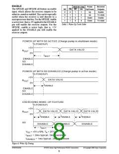
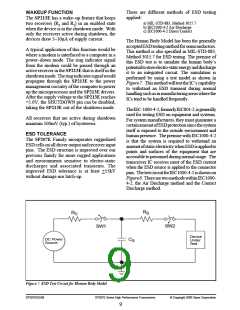
ENABLE
SP213E Only Power
Receiver
Outputs
The SP211E and SP213E all feature an enable
input, which allows the receiver outputs to be
either tri–stated or enabled. This can be especially
useful when the receiver is tied directly to a
microprocessor data bus. For the SP211E, enable
isactive low; that is, 0Vappliedtothe ENABLE
pin will enable the receiver outputs. For the
SP213E, enable is active high; that is, +5V
applied to the ENABLE pin will enable the
receiver outputs.
SD EN SD
EN
1
Up/Down
Up
0
0
1
1
0
1
0
1
1
1
0
0
Enable
Tri–state
Enable
0
Up
1
Down
Down
0
Tri–state
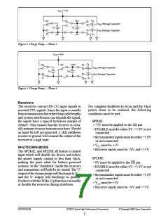
Table 2. Wake–Up Truth Table
POWER UP WITH SD ACTIVE (Charge pump in shutdown mode)
t
0 (POWERUP)
+5V
DATA VALID
R
OUT
0V
t
WAIT
ENABLE
SD
DISABLE
POWER UP WITH SD DISABLED (Charge pump in active mode)
t
0 (POWERUP)
+5V
DATA VALID
R
OUT
0V
t
ENABLE
ENABLE
SD
DISABLE
EXERCISING WAKE–UP FEATURE
t
0 (POWERUP)
+5V
DATA VALID
DATA VALID
DATA VALID
R
OUT
0V
t
t
t
ENABLE
ENABLE
ENABLE
SD
DISABLE
ENABLE
DISABLE
t
WAIT
V
= +5V ±10%; T = 25°C
A
CC
t
t
= 2ms typical, 3ms maximum
WAIT
ENABLE
= 1ms typical, 2ms maximum
Figure 6. Wake–Up Timing
SP207EDS/09
SP207E Series High Performance RS232 Transceivers
© Copyright 2000 Sipex Corporation
8

 SIPEX [ SIPEX CORPORATION ]