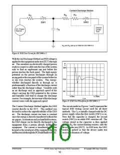
For the Human Body Model, the current limiting
resistor (RS) and the source capacitor (CS) are
1.5kΩan100pF, respectively. ForIEC-1000-4-2,
the current limiting resistor (RS) and the source
capacitor (CS) are 330Ω an 150pF, respectively.
The RS-232 is a relatively slow data exchange
protocol, with a maximum baud rate of only
20kbps, which can be transmitted over a
maximum copper wire cable length of 50 feet.
The SP207E through SP213E Series of data
communications interface products have been
designed to meet both the EIA protocol
standards, and the needs of the industry.
The higher C value and lower RS value in the
IEC1000-4-2 Smodel are more stringent than the
HumanBodyModel. Thelargerstoragecapacitor
injectsahighervoltagetothetestpointwhenSW2
is switched on. The lower current limiting resistor
increases the current charge onto the test point.
EIA STANDARDS
The Electronic Industry Association (EIA)
developed several standards of data transmission
which are revised and updated in order to meet
the requirements of the industry. In data
processing, there are two basic means of
communicatingbetweensystemsandcomponents.
The RS--232 standard was first introduced in
1962 and, since that time, has become an
industry standard.
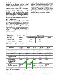
DEVICE PIN
TESTED
HUMAN BODY
MODEL
IEC1000-4-2
Air Discharge Direct Contact
Level
Driver Outputs
Receiver Inputs
+15kV
+15kV
+15kV
+15kV
+8kV
+8kV
4
4
Table 3. Transceiver ESD Tolerance Levels
Specification
RS–232D
RS–423A
RS–422
RS–485
RS–562
Mode of Operation
Single–Ended
Single–Ended
Differential
Differential
Single–Ended
No. of Drivers and Receivers
Allowed on One Line
1 Driver
1 Receiver
1 Driver
10 Receivers
1 Driver
10 Receivers
32 Drivers
32 Receivers
1 Driver
1 Receiver
Maximum Cable Length
50 feet
4,000 feet
4,000 feet
4,000 feet
C ≤ 2,500pF @ <20Kbps;
C ≤1,000pF @ >20Kbps
64Kb/s
Maximum Data Rate
20Kb/s
100Kb/s
10Mb/s
10Mb/s
Driver output Maximum Voltage
±25V
±6V
–0.25V to +6V
–7V to +12V
–3.7V to +13.2V
Driver Output Signal Level
Loaded
Unloaded
±5V
±15V
±3.6V
±6V
±2V
±5V
±1.5V
±5V
±3.7V
±13.2V
Driver Load Impedance
3 – 7Kohm
450 ohm
100 ohm
54 ohm
3–7Kohm
Max. Driver Output Current
(High Impedance State)
Power On
±100µA
±100µA
Power Off
V
MAX
/300
100µA
±100µA
Slew Rate
30V/µs max.
±15V
Controls Provided
±12V
30V/µs max.
±15V
Receiver Input Voltage Range
Receiver Input Sensitivity
Receiver Input Resistance
–7V to +7V
±200mV
–7V to +12V
±200mV
±3V
±200mV
±3V
3–7Kohm
4Kohm min.
4Kohm min.
12Kohm min.
3–7Kohm
Table 4. EIA Standard Definitions
SP207EDS/09
SP207E Series High Performance Transceivers
© Copyright 2000 Sipex Corporation
11

 SIPEX [ SIPEX CORPORATION ]