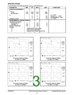
V
= +5V
CC
C
+5V
4
+
–
+
V
V
Storage Capacitor
Storage Capacitor
DD
+
–
+
–
C
C
2
1
–
SS
C
–5V
–5V
3
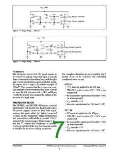
Figure 4. Charge Pump — Phase 3
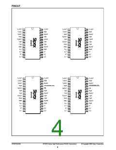
V
= +5V
CC
C
+10V
4
+
–
V
V
Storage Capacitor
Storage Capacitor
DD
SS
+
–
+
–
C
C
2
1
+
3
–
C
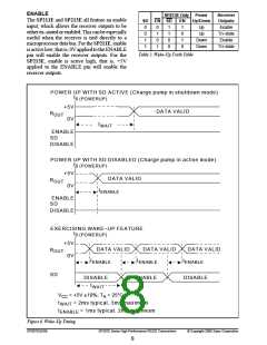
Figure 5. Charge Pump — Phase 4
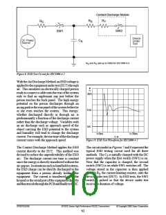
Receivers
For complete shutdown to occur and the 10µA
power drain to be realized, the following
conditions must be met:
The receivers convert RS-232 input signals to
inverted TTL signals. Since the input is usually
fromatransmissionlinewherelongcablelengths
and system interference can degrade the signal,
the inputs have a typical hysteresis margin of
500mV. This ensures that the receiver is virtu-
ally immune to noisy transmission lines. Should
an input be left unconnected, a 5kΩ pulldown
resistor to ground will commit the output of the
receiver to a high state.
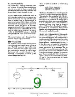
SP211E:
• +5V must be applied to the SD pin
• ENABLE must be either 0V, +5.0V or not
connected
• the transmitter inputs must be either +5.0V
or not connected
• VCC must be +5V
• Receiver inputs must be >0V and <+5V
SHUTDOWN MODE
The SP211E, and SP213E all feature a control
input which will disable the device and reduce
the power supply current to less than 10µA,
making the parts ideal for battery–powered
systems. In the “shutdown” mode the receivers
and transmitters will both be tri–stated. The V+
output of the charge pump will discharge to VCC,
and the V– output will discharge to ground.
Products with the Wake-Up function can enable
or disable the receivers during shutdown.
SP213E:
• 0V must be applied to the SD pin
• ENABLE must be either 0V, +5.0V or not
connected
• the transmitter inputs must be either +5.0V
or not connected
• VCC must be +5V
• Receiver inputs must be >0V and <+5V
SP207EDS/09
SP207E Series High Performance Transceivers
© Copyright 2000 Sipex Corporation
7

 SIPEX [ SIPEX CORPORATION ]