V
= +5V
CC
C
+10V
4
+
–
+
V
V
Storage Capacitor
Storage Capacitor
DD
+
–
+
–
C
C
2
1
–
SS
C
3
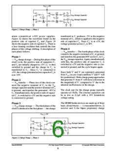
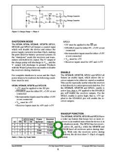
Figure 5. Charge Pump — Phase 4
SHUTDOWN MODE
SP213:
The SP200, SP206, SP206B, SP207B, SP211,
SP211B and SP213 all feature a control input
which will disable the device and reduce the
power supply current to less than 10µA, making
the parts ideal for battery–powered systems. In
the “shutdown” mode the receivers and trans-
mitters will both be tri–stated. The V+ output of
the charge pump will discharge to VCC, and the
V– output will discharge to ground. Products
with the WakeUp function can enable or disable
the receivers during shutdown.
• 0V must be applied to the SD pin
• ENABLE must be either 0V, +5.0V or not
connected
• the transmitter inputs must be either +5.0V
or not connected
• VCC must be +5V
• Receiver inputs must be >0V and <+5V
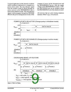
ENABLE
The SP206/B, SP207/B, SP211 and SP213 all
feature an enable input, which allows the re-
ceiver outputs to be either tri–stated or enabled.
This can be especially useful when the receiver
is tied directly to a microprocessor data bus. For
the SP206/B, SP207/B and SP211, enable is
active low; that is, 0V applied to the ENABLE
pin will enable the receiver outputs. For the
SP213, enable is active high; that is, +5V ap-
plied to the ENABLE pin will enable the re-
ceiver outputs.
For complete shutdown to occur and the 10µA
power drain to be realized, the following condi-
tions must be met:
SP200, SP206/B, SP207B and SP211/B:
• +5V must be applied to the SD pin
• ENABLE must be either 0V, +5.0V or not
connected
• the transmitter inputs must be either +5.0V
or not connected
• VCC must be +5V
• Receiver inputs must be >0V and <+5V
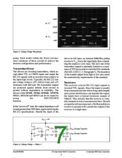
WAKEUP FUNCTION
TheSP206B,SP207B,SP211BandSP213have
a wake–up feature that keeps two or more re-
ceivers in an enabled state when the device is in
the shutdown mode. The SP213 has two receiv-
ers active (R4 and R5), while the SP207B and
SP211B have all receivers active during shut-
down. With only the receivers active during
shutdown, the devices draw 5–10µA of supply
current.
SP213 Only
Power
Receiver
Outputs
Enable
Tri–state
Enable
SD EN SD
EN
1
Up/Down
0
0
1
1
0
1
0
1
1
1
0
0
Up
Up
Down
Down
0
1
0
Tri–state
Table 2. Wake–Up Truth Table
Date:05/26/2005
+5V High-Speed RS232 Transceivers
© Copyright 2005 Sipex Corporation
8

 SIPEX [ SIPEX CORPORATION ]