EFM32G Data Sheet
TQFP48 Package Specifications
9. TQFP48 Package Specifications
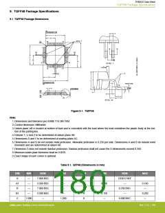
9.1 TQFP48 Package Dimensions
Figure 9.1. TQFP48
Note:
1. Dimensions and tolerance per ASME Y14.5M-1994
2. Control dimension: Millimeter
3. Datum plane AB is located at bottom of lead and is coincident with the lead where the lead existsfrom the plastic body at the bot-
tom of the parting line.
4. Datums T, U and Z to be determined at datum plane AB.
5. Dimensions S and V to be determined at seating plane AC.
6. Dimensions A and B do not include mold protrusion. Allowable protrusion is 0.250 per side. Dimensions A and B do include mold
mismatch and are determined at datum AB.
7. Dimension D does not include dambar protrusion. Dambar protrusion shall not cause the D dimensionto exceed 0.350.
8. Minimum solder plate thickness shall be 0.0076.
9. Exact shape of each corner is optional.
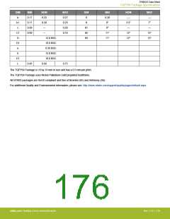
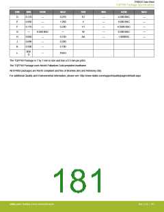
Table 9.1. QFP48 (Dimensions in mm)
DIM
A
MIN
—
NOM
MAX
—
DIM
M
N
MIN
—
NOM
12DEG REF
—
MAX
7.000 BSC
3.500 BSC
7.000 BSC
3.500 BSC
—
A1
B
—
—
0.090
—
0.160
—
—
—
P
0.250 BSC
—
B1
C
—
—
R
0.150
—
0.250
—
1.000
1.200
S
9.000 BSC
silabs.com | Building a more connected world.
Rev. 2.10 | 180

 SILICON [ SILICON ]