C8051F52x-53x
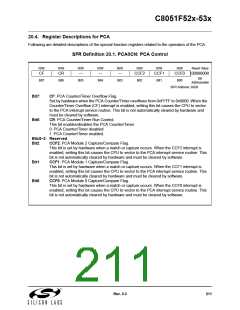
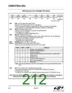
SFR Definition 20.2. PCA0MD: PCA Mode
R/W
R/W
R/W
R
R/W
R/W
R/W
R/W
Reset Value
CIDL
WDTE
WDLCK
-
CPS2
CPS1
CPS0
ECF
01000000
Bit
Bit7
Bit6
Bit5
Bit4
Bit3
Bit2
Bit1
Bit0
Addressable
SFR Address: 0xD9
Bit7:
CIDL: PCA Counter/Timer Idle Control.
Specifies PCA behavior when CPU is in Idle Mode.
0: PCA continues to function normally while the system controller is in Idle Mode.
1: PCA operation is suspended while the system controller is in Idle Mode.
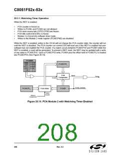
WDTE: Watchdog Timer Enable
If this bit is set, PCA Module 2 is used as the watchdog timer.
0: Watchdog Timer disabled.
Bit6:
Bit5:
1: PCA Module 2 enabled as Watchdog Timer.
WDLCK: Watchdog Timer Lock
This bit locks/unlocks the Watchdog Timer Enable. When WDLCK is set, the Watchdog
Timer may not be disabled until the next system reset.
0: Watchdog Timer Enable unlocked.
1: Watchdog Timer Enable locked.
Bit4:
UNUSED. Read = 0b, Write = don't care.
Bits3–1: CPS2–CPS0: PCA Counter/Timer Pulse Select.
These bits select the timebase source for the PCA counter.
CPS2
CPS1
CPS0
Timebase
System clock divided by 12
System clock divided by 4
Timer 0 overflow
0
0
0
0
0
1
0
1
0
High-to-low transitions on ECI (max rate = system clock
divided by 4)
0
1
1
1
1
1
1
0
0
1
1
0
1
0
1
System clock
*
External clock divided by 8
*
RTC clock divided by 8
Reserved
*Note: External clock divided by 8 and RTC0 clock divided by 8 are synchronized with the system
clock.
Bit0:
ECF: PCA Counter/Timer Overflow Interrupt Enable.
This bit sets the masking of the PCA Counter/Timer Overflow (CF) interrupt.
0: Disable the CF interrupt.
1: Enable a PCA Counter/Timer Overflow interrupt request when CF (PCA0CN.7) is set.
Note: When the WDTE bit is set to ‘1’, the PCA0MD register cannot be modified. To change the
contents of the PCA0MD register, the Watchdog Timer must first be disabled.
212
Rev. 0.3

 SILICON [ SILICON ]