C8051F52x-53x
1.1. CIP-51™ Microcontroller
1.1.1. Fully 8051 Compatible Instruction Set
The C8051F52x/F53xdevices use Silicon Laboratories’ proprietary CIP-51 microcontroller core. The CIP-
51 is fully compatible with the MCS-51™ instruction set. Standard 803x/805x assemblers and compilers
can be used to develop software. The C8051F52x/F53xfamily has a superset of all the peripherals
included with a standard 8052.
1.1.2. Improved Throughput
The CIP-51 employs a pipelined architecture that greatly increases its instruction throughput over the stan-
dard 8051 architecture. In a standard 8051, all instructions except for MUL and DIV take 12 or 24 system
clock cycles to execute, and usually have a maximum system clock of 12-to-24 MHz. By contrast, the CIP-
51 core executes 70% of its instructions in one or two system clock cycles, with no instructions taking more
than eight system clock cycles.
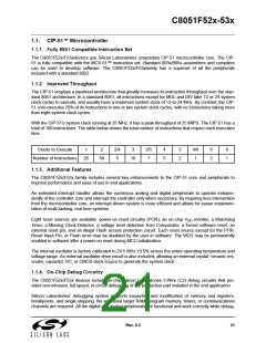
With the CIP-51's system clock running at 25 MHz, it has a peak throughput of 25 MIPS. The CIP-51 has a
total of 109 instructions. The table below shows the total number of instructions that require each execution
time.
Clocks to Execute
1
2
2/4
5
3
3/5
7
4
5
5
2
4/6
1
6
2
8
1
Number of Instructions
26
50
10
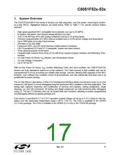
1.1.3. Additional Features
The C8051F52x/F53x family includes several key enhancements to the CIP-51 core and peripherals to
improve performance and ease of use in end applications.
An extended interrupt handler allows the numerous analog and digital peripherals to operate indepen-
dently of the controller core and interrupt the controller only when necessary. By requiring less intervention
from the microcontroller core, an interrupt-driven system is more efficient and allows for easier implemen-
tation of multi-tasking, real-time systems.
Eight reset sources are available: power-on reset circuitry (POR), an on-chip V
monitor, a Watchdog
DD
Timer, a Missing Clock Detector, a voltage level detection from Comparator, a forced software reset, an
external reset pin, and an illegal Flash access protection circuit. Each reset source except for the POR,
Reset Input Pin, or Flash error may be disabled by the user in software. The WDT may be permanently
enabled in software after a power-on reset during MCU initialization.
The internal oscillator is factory calibrated to 24.5 MHz ±0.5% across the entire operating temperature and
voltage range. An external oscillator drive circuit is also included, allowing an external crystal, ceramic res-
onator, capacitor, RC, or CMOS clock source to generate the system clock.
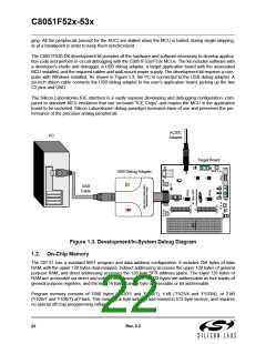
1.1.4. On-Chip Debug Circuitry
The C8051F52x/F53x devices include on-chip Silicon Laboratories 2-Wire (C2) debug circuitry that pro-
vides non-intrusive, full speed, in-circuit debugging of the production part installed in the end application.
Silicon Laboratories’ debugging system supports inspection and modification of memory and registers,
breakpoints, and single stepping. No additional target RAM, program memory, timers, or communications
channels are required. All the digital and analog peripherals are functional and work correctly while debug-
Rev. 0.3
21

 SILICON [ SILICON ]