C8051F52x-53x
20.2.6. 16-Bit Pulse Width Modulator Mode
A PCA module may also be operated in 16-Bit PWM mode. In this mode, the 16-bit capture/compare mod-
ule defines the number of PCA clocks for the low time of the PWM signal. When the PCA counter matches
the module contents, the output on CEXn is asserted high; when the counter overflows, CEXn is asserted
low. To output a varying duty cycle, new value writes should be synchronized with PCA CCFn match inter-
rupts. 16-Bit PWM Mode is enabled by setting the ECOMn, PWMn, and PWM16n bits in the PCA0CPMn
register. For a varying duty cycle, match interrupts should be enabled (ECCFn = 1 AND MATn = 1) to help
synchronize the capture/compare register writes. The duty cycle for 16-Bit PWM Mode is given by
Equation 20.3.
Important Note About Capture/Compare Registers: When writing a 16-bit value to the PCA0 Cap-
ture/Compare registers, the low byte should always be written first. Writing to PCA0CPLn clears the
ECOMn bit to ‘0’; writing to PCA0CPHn sets ECOMn to ‘1’.
(65536 – PCA0CPn)
----------------------------------------------------
DutyCycle =
65536
Equation 20.3. 16-Bit PWM Duty Cycle
Using Equation 20.3, the largest duty cycle is 100% (PCA0CPn = 0), and the smallest duty cycle is
0.0015% (PCA0CPn = 0xFFFF). A 0% duty cycle may be generated by clearing the ECOMn bit to ‘0’.
PCA0CPMn
P
W
M
1
E C C M T
C A A A O
O P P T G
M P N n n
n n n
P
W
M
n
E
C
C
F
n
PCA0CPHn
PCA0CPLn
6
n
1
0 0 0 0
0
SET
CLR
match
CEXn
Enable
16-bit Comparator
S
R
Q
Q
Crossbar
Port I/O
PCA Timebase
PCA0H
PCA0L
Overflow
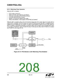
Figure 20.9. PCA 16-Bit PWM Mode
20.3. Watchdog Timer Mode
A programmable watchdog timer (WDT) function is available through the PCA Module 2. The WDT is used
to generate a reset if the time between writes to the WDT update register (PCA0CPH2) exceed a specified
limit. The WDT can be configured and enabled/disabled as needed by software.
With the WDTE bit set in the PCA0MD register, Module 2 operates as a watchdog timer (WDT). The
Module 2 high byte is compared to the PCA counter high byte; the Module 2 low byte holds the offset to be
used when WDT updates are performed. The Watchdog Timer is enabled on reset. Writes to some
PCA registers are restricted while the Watchdog Timer is enabled.
Rev. 0.3
207

 SILICON [ SILICON ]