C8051F52x-53x
20.2.5. 8-Bit Pulse Width Modulator Mode
Each module can be used independently to generate a pulse width modulated (PWM) output on its associ-
ated CEXn pin. The frequency of the output is dependent on the timebase for the PCA counter/timer. The
duty cycle of the PWM output signal is varied using the module's PCA0CPHn capture/compare register.
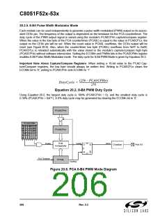
When the value in the low byte of the PCA counter/timer (PCA0L) is equal to the value in PCA0CPLn, the
output on the CEXn pin will be set. When the count value in PCA0L overflows, the CEXn output will be
reset (see Figure 20.8). Also, when the counter/timer low byte (PCA0L) overflows from 0xFF to 0x00,
PCA0CPLn is reloaded automatically with the value stored in the module’s capture/compare high byte
(PCA0CPHn) without software intervention. Setting the ECOMn and PWMn bits in the PCA0CPMn register
enables 8-Bit Pulse Width Modulator mode. The duty cycle for 8-Bit PWM Mode is given by Equation 20.2.
Important Note About Capture/Compare Registers: When writing a 16-bit value to the PCA0 Cap-
ture/Compare registers, the low byte should always be written first. Writing to PCA0CPLn clears the
ECOMn bit to ‘0’; writing to PCA0CPHn sets ECOMn to ‘1’.
(256 – PCA0CPHn)
---------------------------------------------------
DutyCycle =
256
Equation 20.2. 8-Bit PWM Duty Cycle
Using Equation 20.2, the largest duty cycle is 100% (PCA0CPHn = 0), and the smallest duty cycle is
0.39% (PCA0CPHn = 0xFF). A 0% duty cycle may be generated by clearing the ECOMn bit to ‘0’.
PCA0CPHn
PCA0CPMn
P
W
M
1
E C C M T
C A A A O
O P P T G
M P N n n
n n n
P
W
M
n
E
C
C
F
n
PCA0CPLn
6
n
0
0 0 0 0
0
SET
CLR
8-bit
Comparator
match
CEXn
Enable
S
R
Q
Q
Crossbar
Port I/O
PCA Timebase
PCA0L
Overflow
Figure 20.8. PCA 8-Bit PWM Mode Diagram
206
Rev. 0.3

 SILICON [ SILICON ]