C8051F50x-F51x
Table 27.2. PCA0CPM and PCA0PWM Bit Settings for
PCA Capture/Compare Modules
Operational Mode
PCA0CPMn
PCA0PWM
Bit Number
7 6 5 4 3 2 1 0 7 6 5 4–2 1–0
X X 1 0 0 0 0 A 0 X B XXX XX
X X 0 1 0 0 0 A 0 X B XXX XX
X X 1 1 0 0 0 A 0 X B XXX XX
X C 0 0 1 0 0 A 0 X B XXX XX
X C 0 0 1 1 0 A 0 X B XXX XX
X C 0 0 0 1 1 A 0 X B XXX XX
0 C 0 0 E 0 1 A 0 X B XXX 00
0 C 0 0 E 0 1 A D X B XXX 01
0 C 0 0 E 0 1 A D X B XXX 10
0 C 0 0 E 0 1 A D X B XXX 11
1 C 0 0 E 0 1 A 0 X B XXX XX
Capture triggered by positive edge on CEXn
Capture triggered by negative edge on CEXn
Capture triggered by any transition on CEXn
Software Timer
High Speed Output
Frequency Output
8-Bit Pulse Width Modulator (Note 7)
9-Bit Pulse Width Modulator (Note 7)
10-Bit Pulse Width Modulator (Note 7)
11-Bit Pulse Width Modulator (Note 7)
16-Bit Pulse Width Modulator
Notes:
1. X = Don’t Care (no functional difference for individual module if 1 or 0).
2. A = 1 to enable interrupts for this module (PCA interrupt triggered on CCFn set to 1).
3. B = 1 to enable 8th, 9th, 10th or 11th bit overflow interrupt (Depends on setting of CLSEL[1:0]).
4. C = When set to 0, the digital comparator is off. For high speed and frequency output modes, the
associated pin will not toggle. In any of the PWM modes, this generates a 0% duty cycle (output = 0).
5. D = Selects whether the Capture/Compare register (0) or the Auto-Reload register (1) for the associated
channel is accessed via addresses PCA0CPHn and PCA0CPLn.
6. E = When set to 1, a match event will cause the CCFn flag for the associated channel to be set.
7. All modules set to 8, 9, 10 or 11-bit PWM mode use the same cycle length setting.
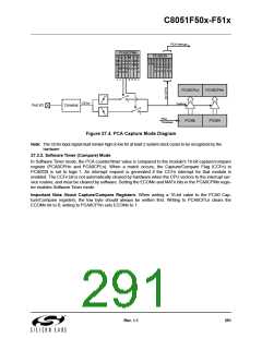
27.3.1. Edge-triggered Capture Mode
In this mode, a valid transition on the CEXn pin causes the PCA to capture the value of the PCA coun-
ter/timer and load it into the corresponding module's 16-bit capture/compare register (PCA0CPLn and
PCA0CPHn). The CAPPn and CAPNn bits in the PCA0CPMn register are used to select the type of transi-
tion that triggers the capture: low-to-high transition (positive edge), high-to-low transition (negative edge),
or either transition (positive or negative edge). When a capture occurs, the Capture/Compare Flag (CCFn)
in PCA0CN is set to logic 1. An interrupt request is generated if the CCFn interrupt for that module is
enabled. The CCFn bit is not automatically cleared by hardware when the CPU vectors to the interrupt ser-
vice routine, and must be cleared by software. If both CAPPn and CAPNn bits are set to logic 1, then the
state of the Port pin associated with CEXn can be read directly to determine whether a rising-edge or fall-
ing-edge caused the capture.
290
Rev. 1.1

 SILICON [ SILICON ]