C8051F39x/37x
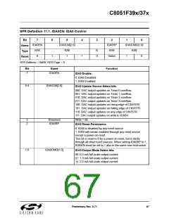
SFR Definition 11.1. IDA0CN: IDA0 Control
Bit
7
6
5
4
3
2
1
0
IDA0EN
IDA0CM[2:0]
IDA0RP
IDA0OMD[1:0]
R/W
Name
Type
Reset
R/W
0
R/W
1
R
0
R/W
1
1
Varies
1
0
SFR Address = 0xB9; SFR Page = 0
Bit
Name
Function
7
IDA0EN
IDA0 Enable.
0: IDA0 Disabled.
1: IDA0 Enabled.
6:4
IDA0CM[2:0]
IDA0 Update Source Select bits.
000: DAC output updates on Timer 0 overflow.
001: DAC output updates on Timer 1 overflow.
010: DAC output updates on Timer 2 overflow.
011: DAC output updates on Timer 3 overflow.
100: DAC output updates on rising edge of CNVSTR.
101: DAC output updates on falling edge of CNVSTR.
110: DAC output updates on any edge of CNVSTR.
111: DAC output updates on write to IDA0H.
3
2
Reserved
IDA0RP
Write = 0b.
IDA0 Reset Persistence.
0: IDA0 is disabled by any reset source.
1: IDA0 will remain enabled through any reset source
except a power-on-reset.
This bit is reset to 0 by a power on reset, but is sticky
through all other reset sources. When setting IDA0RP to 1,
IDA0EN must be set to 1 also in the same mov instruction.
1:0
IDA0OMD[1:0]
IDA0 Output Mode Select bits.
00: 0.5 mA full-scale output current.
01: 1.0 mA full-scale output current.
1x: 2.0 mA full-scale output current.
Preliminary Rev. 0.71
67

 SILICON [ SILICON ]