140dB Range (1nA to 10mA)
SGM834A
Logarithmic Current-to-Voltage Converter
DETAILED DESCRIPTION
and temperature dependence, the VBE1 - VBE2 is
Conversion Operating Principle
temperature and process independent at the intercept
point (note that IREF/IZ is a constant).
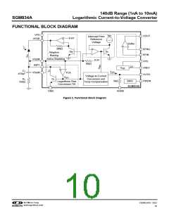
Figure 2 shows the block diagram of the SGM834A,
including the logarithmic conversion blocks and the
required compensations blocks for law conformance.
The Q1 collector voltage is stabilized at 0.5V by a
closed loop bias circuit. The 0.5V is an optimal voltage
level for biasing the photodiode anode, and provides a
good compromise between the diode ohmic leakage
current errors that are significant at lower currents and
the diode series resistance errors that are significant at
higher currents. The adaptive bias block tries to keep
the reverse bias across the diode junction to almost
stable 0.1V by increasing the bias voltage at higher IPD
currents to compensate the diode bulk resistive drops.
The inherent relationship of the collector current (IC)
and the base-emitter voltage (VBE) in a bipolar
transistor (like Q1) is expressed as:
VBE1 - VBE2 = kT/q × loge(IPD/IREF
)
(3)
However, at other currents, the relationship of VBE1
-
VBE2 to IC is still temperature dependent by a direct
multiplication factor (proportional to T). A current mirror
multiplier and a voltage to current conversion multiplier
are used to compensate the temperature variations and
to convert the VBE1 - VBE2 voltage to a temperature and
IS independent current (ILOG). This current passes
through an internal 5kΩ resistor for current to voltage
conversion that provides the intermediate output
voltage (VLOG = 5kΩ × ILOG) with a fixed 200mV/dec
typical slope (200mV increase per one decade or 10×
increase of IPD). The logarithmic conversion is
represented by:
VBE = VT × loge(IC/IS)
VT = kT/q
(1)
(2)
VLOG = 5kΩ × 40μA × log10(IPD/100pA)
= 0.2V × log10(IPD/100pA)
(4)
(5)
where:
log10 (x)
≈ 0.4343
loge (x)
IS is the saturation current of the transistor,
loge is the natural logarithm operator,
VT is the thermal voltage,
log10 is more convenient than loge for per decade units
used for the slope. IZ = 100pA is the SGM834A
intercept current.
k is the Boltzmann constant (~1.38×10⁻²³J/K),
T is the absolute temperature in Kelvin (K),
q is the electron charge in Coulomb (~1.6×10⁻¹⁹C).
Optical Power Measurement
The photodiode sensitivity defined by quantum
efficiency is the number of electrons emitted as a result
of the received photonic irradiation. Because the
electron velocity is stable in a given electric field, the
number of electrons (photo current) will be proportional
to the incoming optical power. So, the IPD can be
measured and calibrated as an equivalent quantity with
the optical power.
Equation 1 provides the raw logarithmic principle that is
used to convert the diode IPD current flowing in the Q1
collector to the logarithmic voltage VBE1. Note that the
fundamental relationship between VBE and IC can be
scaled by both IS and VT. The IC = IS determines the VBE
= 0 intercept point. The IS and the intercept point are
highly temperature and process dependent and have to
be compensated such that the output is independent of
the IS and T. To compensate the IS variations, an
identical dummy transistor (Q2) with the same
geometrics and process as Q1 is implemented in the
device to generate the reference voltage (VBE2) for the
intercept point by setting its collector current to an
stable and accurate reference current (IREF). The IREF
has an input referenced equalization stabilized around
1μA that is 10000 times higher than the intercept
current (IZ = 100pA typical).
The logarithmic current to voltage conversion facilitates
optical measurement in decibel scaling, in which the
optical power is measured as a ratio to a given
reference power, such as dBm that is the ratio to a
1mW reference. If the system is calibrated such that a
1mW optical power results in 1V output, then if a
measurement reading is 1.2V, the optical power is
calculated from 200mV × log10(P/1mW) = (1.2V - 1V)
equation that results in P/1mW = 10 or P = 10dBm.
Because Q1 and Q2 have the same saturation currents
SG Micro Corp
www.sg-micro.com
FEBRUARY 2022
13

 SGMICRO [ Shengbang Microelectronics Co, Ltd ]